So some might know I'm designing a 6B4G PPP amp. The bias scheme I have now can balance the bias between the both sets of output tubes (on either side of the opt) but not individual tubes (on one side of the opt). So would a resistor and pot from each tube cathode to ground allow me to fine tune each tube in concert with the fixed bias?
Athos
Athos
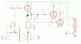
I have the bias supply feeding the grid of a cathode follower driver for each pair of tubes. Does that make sense? This is my first try at at fixed bias amp. Here is the schematic. Post #17 http://www.diyaudio.com/forums/tubes-valves/175100-6b4g-ppp-idea-2.html
Athos
Athos
Is it possible, within the four tubes, or eight if its a stereo amp, you can put reasonably matched pairs together?
I can suggest another way around it, but you may not like it. Ditch the 6SN7 for four mosfet source followers, each with its own bias pot. I'm sure it will sound just as good.
I can suggest another way around it, but you may not like it. Ditch the 6SN7 for four mosfet source followers, each with its own bias pot. I'm sure it will sound just as good.
Ditch the 6SN7 for four mosfet source followers, each with its own bias pot
I've been experimenting with IRFU310 mosfets but still struggling. Had 4 to play with, burnt one of them, and the other 3 seemed to be so unmatched that I need to apply 9/10 more volts on 1 rail to get a balanced/no DC output.
Thought it was unmatched tubes or something else in the chain/driver side.
I started swapping the FETs and the issue followed the FETs.
But as Ian said, try the Fets as described in Tubelabs Powergrid section.
I need to work on my issue more.
Well this may seem weird, considering I have a 10m45 CCS under most elements of my amp, but I was looking for a low tech solution. Originally this was an all tube project, but 6 pentode CCSs was unreasonable and the 10M45 is pretty bullet proof.
What I was thinking was a 10 ohm resistor and a 100 ohm pot. Or, I could double up on the 6SN7s and run one to each 6B4G") , but that would be more work I think.
, but that would be more work I think.
I could get matched tubes but I'm seriously thinking of getting the Soviet 6S4S (6C4C).
Athos
What I was thinking was a 10 ohm resistor and a 100 ohm pot. Or, I could double up on the 6SN7s and run one to each 6B4G
, but that would be more work I think.I could get matched tubes but I'm seriously thinking of getting the Soviet 6S4S (6C4C).
Athos
Last edited:
You can have many pots (and parallel output tubes)
across the diode mentioned above. Still only needing
just one 6SN7, Voltage drop diode, and CCS per side.
hehe, yeah, complexity no matter which way I go
. Thanks for your contribution, I'll see if I can puzzle it out.Athos
So some might know I'm designing a 6B4G PPP amp. The bias scheme I have now can balance the bias between the both sets of output tubes (on either side of the opt) but not individual tubes (on one side of the opt). So would a resistor and pot from each tube cathode to ground allow me to fine tune each tube in concert with the fixed bias?
Athos
As far as I have seen it is not necessary and doesn't bring advantages. I have done it for a 2A3 PSE and there is no practical difference in terms of THD, IMD and sound between individually biased 2A3's (each one with its own cathode follower driver) and both 2A3's biased by a single cathode follower.
Therefore in the PPP case a nice dynamic balance between the two sides of the PP is by far the most important thing (i.e. getting the best square wave response at low frequency, 40 Hz for instance), IMHO. This usually requires a small gap in the OPT to take into account small differences in terms of DC currents, too.
45
Interesting, thanks for the real world experience. I would like to keep the overall complexity down. What OPTs did you use?
Athos
Interesting, thanks for the real world experience. I would like to keep the overall complexity down. What OPTs did you use?
Athos
Lundahl 1627.
It is basically the same transformer for both PP and SE except the gap.
If you use the SE version for a PP the headroom will be the same if no DC unbalance however if (more likely) you have some DC unbalance having that gap is a lot better. The lower primary inductance is not a problem at all. Actually, if you have a gap, you will get nearly the same low end response from a fraction of 1 watt to the max Pout while usually the low-end cut-off is a function of the output level in un-gapped OPT's and inductance drops quickly in presence of DC unbalance. This because, without a gap, you have a larger variation of the core permeability as function of the AC induction (which in turn is proportional to the signal) and DC unbalance.
In many PP OPT's without gap you can re-arrange the core with a small gap. How big the gap depends on the specific case but you can find the final solution trying different sizes (small fraction of mm, usually).
45
I agree with 45....This is important consideration of using gap...but you still need to be sure you have enough inductance to make it down to lowest frequency of interest...
The whole issue with using balancing pot for the DC current has it's limits.... Keep in mind that the output transformer may be happy when it has canceled DC flux but an even bigger issue is the skew of the transconductance across the Push-Pull halves may be even more of an issue.... For example you have an output stage with -42V on one side and -50V on the other side needed to balance the DC....now you will have one side clipping sooner than the other.... The AC imbalance can be corrected for, provided you have enough headroom in the gain of the feedback loop for error correction...
Chris
Lundahl 1627
Well that's not going to happen
. The $50 buck Edcors are where it's at...Well that's not going to happen
That was just the answer to your question. You can have a gap on the Edcor as well. You just need to find the practical solution which means enough inductance together with enough headroom in case of DC unbalance. You can start trying with 0.05-0.1 mm.
In your case you also have 8 power tubes to play with and I am pretty sure that if they measure within 10% one from any other for current and mutual conductance it will be easy and straightforward to make pairs so that you can find dynamic balance with little adjustment together with good DC balance using a single bias network for each pair.
45
- Status
- This old topic is closed. If you want to reopen this topic, contact a moderator using the "Report Post" button.
- Home
- Amplifiers
- Tubes / Valves
- Mixed bias for balancing unmatched tubes in PPP?