Hi friends,
I want to build a UCD with the following specs:
freq=250kHz.
s/woofer = JBL CS1215, 4 ohms, 275W max.
req amp power = 200W.
Unfortunately, i have no access to an oscillioscope . and would like to get help on the following:
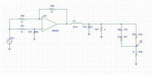
1) How to calculate values L, C for output filter?
2) Is a gain of 56 problematic?
3) How to provide the GD power supply with good peak-current capability?
4) How to work out values for the resistors around the level-shift transistor?
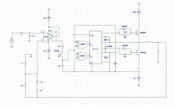
Schematic attached.
Thanks in advance.
I want to build a UCD with the following specs:
freq=250kHz.
s/woofer = JBL CS1215, 4 ohms, 275W max.
req amp power = 200W.
Unfortunately, i have no access to an oscillioscope
. and would like to get help on the following:1) How to calculate values L, C for output filter?
2) Is a gain of 56 problematic?
3) How to provide the GD power supply with good peak-current capability?
4) How to work out values for the resistors around the level-shift transistor?
Schematic attached.
Thanks in advance.
Attachments
@newvirus2008
related to question 4 try this:
http://ufdemo.uni-information.com/audio/pictures/level-shift.gif
it is from here:
http://www.diyaudio.com/forums/class-d/166214-ucd-25-watts-1200-watts-using-2-mosfets-11.html
regards,
savu
related to question 4 try this:
http://ufdemo.uni-information.com/audio/pictures/level-shift.gif
it is from here:
http://www.diyaudio.com/forums/class-d/166214-ucd-25-watts-1200-watts-using-2-mosfets-11.html
regards,
savu
If this is only for sub application, why go 250kHz? 50 kHz is way enough!
reg 1) : if only one pre-defined load (woofer) is to be applied, it is relatively easy to find good LC values. In fact, this gets even more easy as the factor between your LF bandwith (assuming <=200Hz) and your fs is sooo big.
reg 1) : if only one pre-defined load (woofer) is to be applied, it is relatively easy to find good LC values. In fact, this gets even more easy as the factor between your LF bandwith (assuming <=200Hz) and your fs is sooo big.
Yes savu, I want it to be around 250kHz!
I will be initially testing it with full range audio and ordinary speaker, so i want it to be 250kHz. I mentioned 's/w' so that the target distortion levels are clearly understood.
thank you Vienna tom, but would you please share your idea on getting LC values for the filter?
I will be initially testing it with full range audio and ordinary speaker, so i want it to be 250kHz. I mentioned 's/w' so that the target distortion levels are clearly understood.
thank you Vienna tom, but would you please share your idea on getting LC values for the filter?
Last edited:
Do you think you need some special LC filter because it's going to be subamp ? No, you are wrong. Use 30uH and 680nF. These values are used typically ( at least in diy ).
If you want to use it as subwoofer amp, then you need active low pass filter on the input side. Btw.
Lout = Rsp / (2 x Pi x Frolloff), Pi=3.14
Cout = Lout / (4 x Rsp x Rsp x K x K ), K=0.707 typically value.
If you want to use it as subwoofer amp, then you need active low pass filter on the input side. Btw.
Lout = Rsp / (2 x Pi x Frolloff), Pi=3.14
Cout = Lout / (4 x Rsp x Rsp x K x K ), K=0.707 typically value.
Last edited:
"thank you Vienna tom, but would you please share your idea on getting LC values for the filter? "
I can propose a good starting point for LC filter values if u tell me exactly what load impedance (min and max) and what bandwidth (sub or full range?) it should be designed to. I assume fs in your design will be ~250kHz, but for full range, 400kHz is better, especially with varying load impedance this would give more freedom to choose L C values...
BTW: I really dislike the old mosfet type you have choosen.... there is many way better parts (try to seek for parts with as low body diode reverse recovery as possible as well as low Rdson while the Qg is still reasonably low). Save 2 or 3 bucks on the heatsink and invest 3 bucks on better FETs - this can push efficiency up at no extra cost, but u get smaller size and weight.....
@savu:
-> if it is designed as a subwoofer, then it does not matter what kind of music is played (dubstep or drum and bass...) - a subwoofer is is defined by the limited bandwidth, otherwise it is not a subwoofer ...
->the big advantage of going 50kHz for pure sub app is an 80% reduction in switching losses vs. 250kHz (-> less consumption, less heat, more output power at equal heatsink size,...)
i want to test the amp using fullrange audio and after everything is fine and working, will setup in s/woofer format with all front end filter LR transform etc.
Also, i believe LC values come from switching freq attaining 180 round trip phase thats why i am askng for design. At 50kHz, the LC values can be quite large isnt it?
And mtech, i have no probs at all using 30u and 680n! i ll only be happy if its that easy.
Sorry vienna tom, my voice coil resistance is 3.6 ohm and 2.57millihenries. i have difficulties finding good mosfets in the local market.
IRF540, 640, IRF150, IRFP250 and all beefy things available here. Any need to lower rds, i am ready to parallel. thanks.
Last edited:
PLEASE - no parallelling of old junkFETs - look at the latest low voltage Trench-Series of the different vendors FSC, STM, IR, Infineon, Vishay,....
Think: 100 V TO220 is available down to less than 4 (!!!) mOhms now
http://www.fairchildsemi.com/ds/FD/FDP036N10A.pdf
I do not recommend this type, but listen: take this as a starting point for thinking and search for devices with smaller chip size (same case). As you go smaller chip size (=higher RDson) keeping the same latest trench technology you get: 1 lower cost, 2 lower reverse recovery, lower Qg... lots of advantages - maybe you ll find your optimum part at...say somewhere between 10 and 30mOhms - there is tons of available and cheap FETs out there.
If that is your only load impedance (very high ohmic at the resonant LC frequency), i d start with slightly higher filter impedance (e.g. 39u, 470n). BUT: if the woofer is the only load then the design for 20kHz does not make sense, otherwise it would not be the only load, but some kind of passive X-over and woofer / midrange / tweeter combination....
My only load is the s.woofer. but i may connect other full range for initial testing only. My regular use will be with s.woofer only.
Here in my place i get only devices that are spare parts of inverters, TVs etc.
I wont even find a toroidal inductor in the local market here. I will have to get it from some psu.
Cant i get away with any of the regular IR types like IRF540(77mohm) or IRF150 (55mohm)?
Here in my place i get only devices that are spare parts of inverters, TVs etc.
I wont even find a toroidal inductor in the local market here. I will have to get it from some psu.
Cant i get away with any of the regular IR types like IRF540(77mohm) or IRF150 (55mohm)?
Last edited:
"Cant i get away with any of the regular IR types like IRF540(77mohm) or IRF150 (55mohm)?"
You calculate it: Switching & reverse recovery losses plus on losses (use RMS mosfet current for calc. and assume high temp -> worse FET behavior) times Rtherm J-ambient gives heat rise in K. Define ambient temp and define heatsink / coolong and you ll see if you can get away...
its as easy as that.
I d also have some many different FET devices at hand here, but they'd come expensive to you because of shipping n handling. .
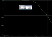
Sim for phase shift analysis
Hello newvirus2008,
I use this simulation to estimate the switching frequency of a UCD. You may find similar graph from original UCD paper.
Cheers,
Hello newvirus2008,
I use this simulation to estimate the switching frequency of a UCD. You may find similar graph from original UCD paper.
Cheers,
Attachments
Hi gogo,
Got it man! But the problem with me was that i was using PSPICE schematics and orcadwhich does nt have any option to delay analogue signals such as sinusoids (to my best k'ledge). But you have it there in LTspice.
However if you re familiar with schematics, please tell me how to implelement delay of 400ns.
Your design seems to oscillate between 500kHz and 600kHz, is that right?
Last edited:
Hi gogo,
Got it man! But the problem with me was that i was using PSPICE schematics and orcadwhich does nt have any option to delay analogue signals such as sinusoids (to my best k'ledge). But you have it there in LTspice.
However if you re familiar with schematics, please tell me how to implelement delay of 400ns.
Your design seems to oscillate between 500kHz and 600kHz, is that right?
Sorry I don't know how to use Orcad.
The delay is the total delay of comparator, level shifter, drivers and mosfet output. The signal once leave the comparator becomes a square one instead of sinusoidal.
I learned ltspice model of delay from this thread.
http://www.diyaudio.com/forums/class-d/159707-ltspice-delay.html
Actually you can play with the ltspice file I attached in my previous post.
The schematic I posted is not an actual one but just picking up some parameters from yours. Yes, you're right. It should oscillate between 500K-600KHz.
What I've actually done was that, I built a UCD circuit without closing the feedback loop, measured the actual delay by injecting square signal into the comparator, use the simulation to design the parameter of the Phase Lead network, and finally fine tuned it experimentally. You need a scope to do so though.
Cheers,
Is that right ?
Just read 500 or 600 instead of 455kHz.
And the phase lead n/w is to push the phase crossover freq to the desired value........okokok
Even i think i ll need a scope
Just read 500 or 600 instead of 455kHz.
And the phase lead n/w is to push the phase crossover freq to the desired value........okokok
Even i think i ll need a scope
Attachments
Last edited:
- Status
- This old topic is closed. If you want to reopen this topic, contact a moderator using the "Report Post" button.
- Home
- Amplifiers
- Class D
- Ucd for s/woofer appln