Hi,
I am designing a tube preamp fed by a choke filtered supply, followed by a shunt regulator. Much fun!
Due to this setup, any failure in the preamp section lowers the current in the power supply and the voltage rises. Now, I will install overrated filter capacitors after the choke, but in a serious case of failure (when one complete channel drops out), the voltage rises above the rated value.
So, I feel the need to protect the PSU capacitors agains overvoltage (>400V). I have seen some transistor based circuits, shunting extra current to regulate to a safe potential, but this is not an option as I suspect oscillations with the other shunt regulators, and above all it is complicated. I want to keep it simple with a voltage detection circuit and a relay that switches off the complete High Voltage section, and will reset after manual power off. To supply this circuit a second regulated low voltage supply is already available in the power section.
Does anyone have experience with this kind of overvoltage protection circuits?
Cheers, Pete
comparator, or even window comparator.
Use this to detect over/under voltage and send signal to relay triggering circuit.
A shunt regulator set to above the normal working voltage would also work. It would not normally regulate but when going towards overvoltage it turns itself on automatically. It could even send a signal to a flashing indicator to tell you that one channel has gone dead! or more usefully to trigger that relay.
Hello Andrew,
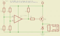
Thanks for the tip. I have never worked with a comparator, but after a quick study, I came up with the following circuit. This is what I was looking for.
The High Voltage circuit is normally regulated at 350V. In case of overvoltage (>400V) the IN+ port reaches >6V, the comparator switches a relay circuit to turn the HV supply off, and so protecting HV electronics, and possibly the user (me).
I will use a double latching relay, and use a manual switch to reset the relay after the circuit has initiated the protection mode and the cause of failure is fixed.
Am I correct that I could use a NPN transistor instead of the PNP (IC2) if I swap the inputs of the LM393?
Does anyone have remarks on this circuit? I will test this soon and share the results here.
Attachments
- Status
- This old topic is closed. If you want to reopen this topic, contact a moderator using the "Report Post" button.