I have a DVD Nav Headunit in my Lancer and i want to add aftermarket amps to the radio.. But as you know most factory radios dont have rca out.. line-level out.. So I opened up the unit found the AMP IC and followed the imput to some "4580" jrc chips two of them.. can i solder my rca wires to the output.. do i need diodes capacitors etc this is a car radio..
Thanks for the help..
Thanks for the help..
That's a NJM4580 dual op-amp. It's probably line level out (ie RCA in this case). Whether or not you need capacitors or other parts depends on the circuit surrounding the op-amp.
Given that it's used in a car environment, you should put a capacitor (try 22uF 50V electrolytic) in series with the output followed by a resistor (try ~22k ohm) to ground.
Given that it's used in a car environment, you should put a capacitor (try 22uF 50V electrolytic) in series with the output followed by a resistor (try ~22k ohm) to ground.
Last edited:
That's a NJM4580 dual op-amp. It's probably line level out (ie RCA in this case). Whether or not you need capacitors or other parts depends on the circuit surrounding the op-amp.
Given that it's used in a car environment, you should put a capacitor (try 22uF 50V electrolytic) in series with the output followed by a resistor (try ~22k ohm) to ground.
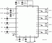
It looks like it uses the NJM4580 as a line driver for the TDA7386 AMP.. I dont plan on using the built in power at all so the amp will not have speakers pluged in.. But i do want to use the NJM4580 to output to RCA.. I found pins 11, 12, 14, and 15 to be the Line-IN at that amp ic and pin13 sig ground.. I was just thinking of putting 4 rca cables on pin 11,12,14,15 and ground all of them to pin 13..
Here are some pics i took so you can see what im looking at.. I know the cap the brown ones near the amp run in serial with the am imput one for each they say 224


Thanks for the info..
It looks to me like C107, C127, C147, C167 are all electrolytics in series with the output of the op-amps to block DC.
10uF series -> resistor to ground -> resistor series -> muting transistor -> resistor series -> capacitor to ground -> brown capacitors? (0.22uF)
It's a very typical line out circuit. You can certainly tie some RCA outputs to the TDA7386 input pins. You may be able to find a better (easy to solder) ground point than pin 13. Just probe around likely spots and check for continuity to pin 13.
Last edited:
Actually, those caps are probably on the input pins, as shown here:
The outputs are bridged.
Yes the brown capacitors @ c169, c129, c109 and c149 are on the inputs to the TDA7386 so get the signal after the caps or before?
if the -> in brown caps -> tda7386
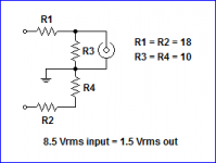
Here's a thought too: If it was me, I'd prefer not to go into the internals of the head unit. Why not build a simple spkr-to-line-level convertor? With the right selection of resistors, you can keep the TDA7386 down in the 1-watt range, which keeps the THD below .05%. That would be fine in a car environment, and you can adjust the resistor values to get whatever output voltage level you prefer.
Here's one way: (Btw, you want to balance the two speaker-wire output loads since this device is "bridged".)
The two inputs are LF+/LF- speaker outputs. Obviously, you'ld need four of these circuits.
Here's one way: (Btw, you want to balance the two speaker-wire output loads since this device is "bridged".)
The two inputs are LF+/LF- speaker outputs. Obviously, you'ld need four of these circuits.
Attachments
Last edited:
Here's a thought too: If it was me, I'd prefer not to go into the internals of the head unit. Why not build a simple spkr-to-line-level convertor? With the right selection of resistors, you can keep the TDA7386 down in the 1-watt range, which keeps the THD below .05%. That would be fine in a car environment, and you can adjust the resistor values to get whatever output voltage level you prefer.
Here's one way: (Btw, you want to balance the two speaker-wire output loads since this device is "bridged".)
The two inputs are LF+/LF- speaker outputs. Obviously, you'ld need four of these circuits.
That is what I had before a "low level converter" but past 1/2 volume we saw distortion on a scope.. plus to me it did not sound good.. i had pop and noise.


well its done now.. I just need to put it back in the car and see what it sounds like I wished I still had access to the scope to see what it does now.. I belive those opamp should be doing around 4volts.. so that should be perfect for my amps..
 bad news.. It works but im only getting .29 volts AC with a test tone cd with a 1kh sine wave. It sounds good but now my gain on the amps are so high i get noise.. even with the volume at 0 i hear hiss..
 Should i remove the built in amp?? Or am I just wasting my time and go back to the resistor pack i had before?
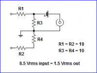
Well, I just realized a mistake I made in the circuit I posted. Which is, the RCA output must be capacitor-coupled in a bridged amp. I had forgotten, (until I put mine on the bench), that both amps idle at around 6-volts DC. One goes positive while the other goes negative. Thats how they get the wide voltage swing. (I knew this, it just slipped my mine when I drew that up.)
So . . . along with the cap, you'ld probably want to do a second or two power-up-delay on the amps to avoid the turn-on thump. I'll mod that drawing, but its still not quite as simple a solution as first meets the eye.
I'm going to breadboard one up, and see if I can work out the bugs.
I can't edit that other post, so here's the "corrected" circuit.
Attachments
Last edited:
Bump this old post - inquiring minds would like to know
Hello, new member here.
Joined up after searching far and wide for the best way to add RCA line level outputs to this Mitsubishi MMCS NAV unit.
Found the TDA7386 data sheet and internal schematics are available on the line, for any of you intern fans out there.
The NAV unit is pricey new around $3K but now many used units are showing up on ebay for a few hundred dollars and they drop right in plug for plug with the standard radio head units. mine plugged in and it is amazing. Found the complete schematics of this thing on google search NR-261UM-07LAN4,-07-5WS and took the link to mmc-manuals.ru
I am trying to learn the best way to pull out a low level line signal for an infinity 4555a amp to drive my 2 tweeters, 4 midrange and the sub in the back.
The infinity will take high level speaker inputs so I guess I could pack up and go home but something about going to the board level and liberating those clean line level inputs preamp has piqued my curiosity.
From what I have read so far pulling the signals from before the TDA7386 in circuit does not have decent amplitude swing for driving a remote amp line input, this was tested on an actual circuit so kudos and OK. I think we can all agree the signal loading is fine with just the TDA7386 as designed.
The other approach presented was load the TDA7386 to keep it operating in the low 0.05% THD regime but no final result was published and I lose my pique not getting a chance to tear in the the NAV unit.
Guess my newbie question is could I open circuit the line inputs to TDA7386 and match the load with a line driver chip or circuit to get a normal response from my infinity amp? Put another way, transport the same line signals to a remote TD7386 without too much loss and distortion.
All ideas appreciated, part numbers are good I like checking out the data sheets, hope this is a common thing for some of you guys. Seen some good pictures in this thread.
Many others over at the Mitsu message boards would love to see final pictures and a circuit that works.
Thanks,
- Status
- This old topic is closed. If you want to reopen this topic, contact a moderator using the "Report Post" button.
- Home
- Amplifiers
- Chip Amps
- 4580 JRC Add Line Out