I have made my new power amplifier. After a long day night working hard on the research for a 2 month. I named it a '"Bee Power Amplifier".
The amplifier is a Class AB type. The result have make me a lot. The simple circuit with great sound is what I'm aiming.
I want to share it with the fan. Any idea or comment from the fan will bring me a lot of new information to me.
The value of the transistor soon will be publish at my own website.
The main porpuse of this is to get the comment from the expert amplifier maker if my design have anything wrong in the value and connection.
I have built the prototype and the end result have prove to worked well but the testing and tools I have cannot check all the result. What I done is a hours off hearing form the loudspeaker of mine.
regards
nanhifi
The amplifier is a Class AB type. The result have make me
a lot. The simple circuit with great sound is what I'm aiming. I want to share it with the fan. Any idea or comment from the fan will bring me a lot of new information to me.
The value of the transistor soon will be publish at my own website.
The main porpuse of this is to get the comment from the expert amplifier maker if my design have anything wrong in the value and connection.
I have built the prototype and the end result have prove to worked well but the testing and tools I have cannot check all the result. What I done is a hours off hearing form the loudspeaker of mine.
regards
nanhifi
Attachments
Has this amplifier 60 watts on a 4 or on an 8 Ohm load?
With +/-40V, 60W into 8ohm seem reasonable..
nanhifi,
You could place a capacitor between emitter and collector of Q8, so that the signal can pass through the capacitor instead of the transistor.
I have something quite similar, but no current mirror on the inputstage, boostrapped VAS (instead of current source), and two pairs of output transistors in parallel. It runs at +/-52V.
I wonder how you have come up with the value of R19 and R20. I'm not sure what the optimum value is? (I use 220R myself)
I would recommend you to mount Q8 on top of Q9 if you haven't done it already. The bias current got very stable when I did that.
/Freddie
P3A similarity
There's nothing wrong with C1 and C5's orientation. Remember C5 is for the inverted feedback signal.
Not implying anything, but this amp is very similar to Rod Elliott's P3A (especially component values). The only difference is a PNP diff amp, current mirror and some small other refinements.
I suspect it should sound quite good considering the quality of the P3A (I've already built 12, progressively changing the design as I go along). Especially the current mirror instead of the normal resistor should be a great improvement. Maybe a Wilson current source could further improve matters. The emitter degeneration resistors can also be reduced a bit without penalty (in fact several diff amps omit them).
All in all a fine amp.
Pierre
PWatts,
You mention that some omit the reducing resistors in the long tain pair.
This will increase open loop gain. If the designer doesn't have that many tools to check the signals with (other than listening) then it can lead into problems.
Considering that the input pair's current is (as usual) low, I'm surprised about the small values (100ohm) of the resistors leading to the current mirror. Wouldn't an increase improve dynamic range/gain for the next stage?
Mvh,
Jens
Hmmm, haven't thought about it that way. You are of course correct. I'll do some SPICE simulations to check the overall effect. Now that you mention it, I've seen values in the kohm range for some. I suspect that simulations should be used to find an optimum value, and then fine tune it by ear.
Pierre
Pierre
An emitter-resistor on Q7 (gain stage) would decrease gain while improving the stage's linearity.
A concern of mine is that unless you have very high current gain in your driver/output devices, there may be a (too low) limit of drive current in the Vas stage (Q7).
I am currently designing my own amp with a stasis-inspired output stage, in the sense that I take the negative feedback (Vfb) from the driver (Vbias) stage, and thereby avoid the phase shift (lag) in the feedback path. I would normally get this when taking the Vfb from the speaker terminal point.
Yes, you get a little less control of the speaker, but response will be faster, and your gain margin ( == stability) will increase.
This, in turn can either be used to have the better margin, or improve bandwidth, or a compromise.
Give it a thought...
Jens
Pwatt,
My reasoning is this. If you assume the output voltage of the amp is zero (as it should be) when there is no input signal, then calculate the static currents flowing through the bases of the diff pair, you should find the voltage at the bases is above zero. As the circuit is drawn this will cause the caps to be reverse biased.
Bam
Hi PWatt,
Regarding C1 it shouldn't matter which way it is orientated, unless you have a source with a DC offset. The amp's input resistors (which I find rather low of value) should fource the input to ground potential, and leave polarization do be determined by the source supplying the sigal.
The feed-back DC potential depends on the amp's circuit (see if you can find it on your simulation). Some cause a positive DC, others a negative, while it should ideally *...cough cough...* be zero volts DC.
Regarding C1 it shouldn't matter which way it is orientated, unless you have a source with a DC offset. The amp's input resistors (which I find rather low of value) should fource the input to ground potential, and leave polarization do be determined by the source supplying the sigal.
The feed-back DC potential depends on the amp's circuit (see if you can find it on your simulation). Some cause a positive DC, others a negative, while it should ideally
*...cough cough...* be zero volts DC.Thanks for all the comment.
megajocke
Will the capacitor C6 of only 220pf really be of any help decoupling the base of the current source? In other amplifiers i have seen values of over 100uF! Maybe you should decouple the LED too?
when omited the C6 and i found there are something wrong of the music. Maybe it just my imigination but when i put the 220pF it seems to be the lovely of my music came back. I do not have any osiloscope or spl meter just a DMM and a pair of my ear. I will try to put the C6 with 100uF after this and get the result.
For the C5 that is hot a disscussion now, I want to omit it. I found that (JHL update ) it will bring a good improvement for the amplifier. There a lot of non linear charecteristic in a caps.
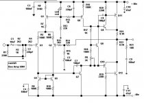
The design base from a source I read from Dougles self, rode elliot, and hundred of basic power amplifier circuit topology. The major circuit originally base from P3A and I then upgrade it. I choose the P3A basic output topology and change the input with a current mirror. I like the sound of P3A not very smooth on the treble and a solid bass. The major problem is still under moderated when I drive it at higher level. I have made the blameless power amplifier bye Dougles Self and yet my ears still cannot accept a smooth treble. I still hate a loud treble.. a big of in the middle I prefer.
Anything all the comment I will do it and get listening on it. I still do not want to change the gain. Before this I use a value of 220K for R14, R15=10K,C5=10uF and R3 220k and it improve the mid vocal of a music. The major problem is to get tha dc offset lower then 100mV. If any idea in this problem.
I use a 2SA970 for the Q1 and Q2 a big hFE and low noise.
I now make it run for class A at bias of 1.8A with slow 3MHz power transistor. The truth is better in overall respond.
thanks for now.. i will get the result soon from your comments..
megajocke
Will the capacitor C6 of only 220pf really be of any help decoupling the base of the current source? In other amplifiers i have seen values of over 100uF! Maybe you should decouple the LED too?
when omited the C6 and i found there are something wrong of the music. Maybe it just my imigination but when i put the 220pF it seems to be the lovely of my music came back. I do not have any osiloscope or spl meter just a DMM and a pair of my ear. I will try to put the C6 with 100uF after this and get the result.
For the C5 that is hot a disscussion now, I want to omit it. I found that (JHL update ) it will bring a good improvement for the amplifier. There a lot of non linear charecteristic in a caps.
The design base from a source I read from Dougles self, rode elliot, and hundred of basic power amplifier circuit topology. The major circuit originally base from P3A and I then upgrade it. I choose the P3A basic output topology and change the input with a current mirror. I like the sound of P3A not very smooth on the treble and a solid bass. The major problem is still under moderated when I drive it at higher level. I have made the blameless power amplifier bye Dougles Self and yet my ears still cannot accept a smooth treble. I still hate a loud treble.. a big of in the middle I prefer.
Anything all the comment I will do it and get listening on it. I still do not want to change the gain. Before this I use a value of 220K for R14, R15=10K,C5=10uF and R3 220k and it improve the mid vocal of a music. The major problem is to get tha dc offset lower then 100mV. If any idea in this problem.
I use a 2SA970 for the Q1 and Q2 a big hFE and low noise.
I now make it run for class A at bias of 1.8A with slow 3MHz power transistor. The truth is better in overall respond.
thanks for now.. i will get the result soon from your comments..
It isn't my experience that C1 and C5 caps will add significant distortion when correctly biased. However, if they are electrolytics, preferably tantalum, they probably won't work well if reverse biased. Electrolytics need a dc offset across them, which will be provided for free by the diff pair bipolars.
At least get a DMM on the case and check the dc voltages are in the right direction.
Good luck!
At least get a DMM on the case and check the dc voltages are in the right direction.
Good luck!
HEllo Nanhifi,
Wou wrote:
...The major problem is still under moderated when I drive it at higher level....
What problem, and what happens. I cannot follow you...?
If your problem with the sound increases with volume, it may be the same problem I encountered when simulating a similar output stage.
I found that the voltage gain section (based on Q7 in your case) could not deliver the current needed for the output stage at higher levels.
Therefore I ended up putting a third transistor stage in the output as an emmitter-follower.
The price was a higher Vvias, which gave me a lower limit on the max output voltage ( ==> less power). However, the amplifier (yet only in the simulator) has become more linear.
As for measuring devices, you should get a volt-meter at the least to check your important levels and off-sets. (as I understand that you don't have yet).
If that is correct that you don't have any measuring help/devices, I am impressed (or you are lucky ) that you made the amplifier work this well
Jens
Wou wrote:
...The major problem is still under moderated when I drive it at higher level....
What problem, and what happens. I cannot follow you...?
If your problem with the sound increases with volume, it may be the same problem I encountered when simulating a similar output stage.
I found that the voltage gain section (based on Q7 in your case) could not deliver the current needed for the output stage at higher levels.
Therefore I ended up putting a third transistor stage in the output as an emmitter-follower.
The price was a higher Vvias, which gave me a lower limit on the max output voltage ( ==> less power). However, the amplifier (yet only in the simulator) has become more linear.
As for measuring devices, you should get a volt-meter at the least to check your important levels and off-sets. (as I understand that you don't have yet).
If that is correct that you don't have any measuring help/devices, I am impressed (or you are lucky
) that you made the amplifier work this well Jens
Regarding the polarity of C1 & C5: Traderbam was correct. the current polarity is correct for an NPN diff amp. For PNP it should be reversed (just do a few KVL calculations). Much better to change C1 to a non-polarized poly cap. 2.2uF or even 1uF should work fine, except if your speakers extend to sub-20Hz frequencies. C5 can be changed to 2x 220uF electros in series and parallelled with a 100nF poly cap for best results & linearity.
- Status
- This old topic is closed. If you want to reopen this topic, contact a moderator using the "Report Post" button.
- Home
- Amplifiers
- Solid State
- Bee Power Ampifier to the test