Working on a design for an amplifier that runs on 12V that I can use with a PC and use the PC's power supply for the 12V.
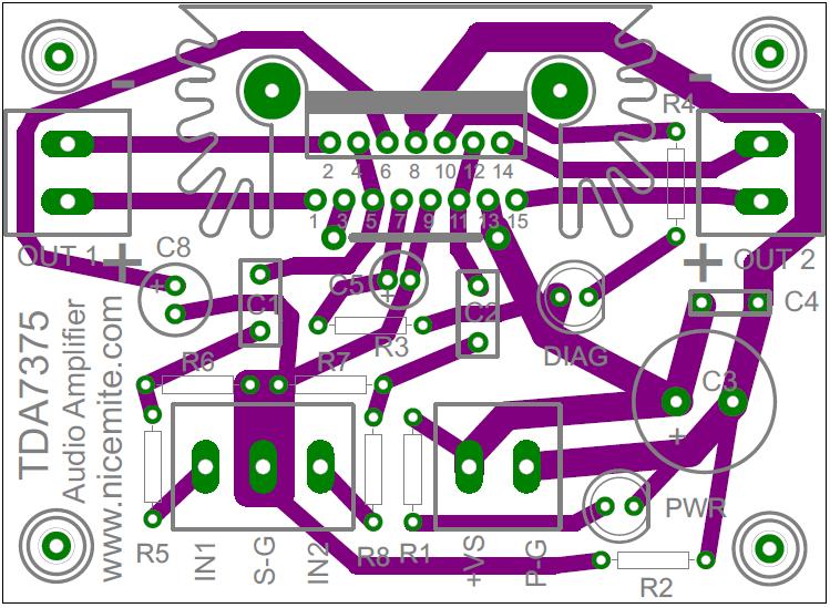
I first built an amp based on TDA7393 but got some pretty bad noise. Turns out I need a chip with separate Power Ground and Signal Ground to break the ground loop between the sound card and the power supply. This lead me to try the TDA7375. Here is the layout. Not much different than the datasheet. Just added a power LED, diagnostic LED, a place for a resistor between the Power and Signal Ground, and two LPads for attenuating the signal since the fixed gain will likely be too high for the sound cards output.
I'll post more as the build progresses.
Attachments
I just got my chips the other day and I plan to have one running in a few days or so.
I don't think that switching chips will solve the noise problem and I will look into this once I get it up and running.
However I am curious as to which chip is better?
I like the specs of the TDA7375 but I think that the TDA7393 might a little more powerful.
Let me know what you find when you get running as I almost opt'ed for the TDA7375 for my little project. jer
TDA7375 Build ---- Help!
UH-OH!
Well, the good news is I built the amp and it worked. I first built it using a jumper at R2 between the signal and power ground instead of the 10 ohm resistor. It worked great but of course had some noise due the the ground loop between the sound card and the power supply.
I changed over from the jumper to the resistor and all I got was static and a solid diagnostic LED. I think that the amp doesn't like the 10 ohm resistor for some reason so I put back in the jumper...still just static and a solid diagnostic LED.
Did I kill the chip by trying the 10 ohm resistor?
I got the idea for the resistor between power and signal ground from this site:
4x15 Watt quad audio amplifier
Different chip, but I thought the same principle would apply.
Any suggestions?
TDA7375 Build ---Success!
Good news today! It wasn't the resistor at R2 that caused the issue. I was turning the amp off and on by plugging in a peripheral cable. The cables are not the best and require some wiggling on occasion to get them together. The intermittent contact is what was ruining the chip...happened twice. I have a switch inline now to cut the power nicely. Good thing I had a few chips to spare.
The better news: the 10 ohm resistor at R2 does its job perfectly. No more noise from using the pc power supply to run the amp. Yay!
Hooked this little guy up to a pair of tower speakers least night instead of the tiny satellite speakers I had been testing with. Tower speakers are nothing special...just some Sonys from Best Buy, but WOW! What a difference. I was really surprised by how nice it sounded and the amount of bass produced. It gives my old receiver a run for its money. I had low expectations going in so I was just looking down at this tiny, simple little amp using the PC's power supply and couldn't believe it was performing as well as it was.
- Status
- This old topic is closed. If you want to reopen this topic, contact a moderator using the "Report Post" button.