Hi guys.
My current speaker project is going well. I had finalised my crossover design until i messed with Boxsim some more, and came up with an alternative design.
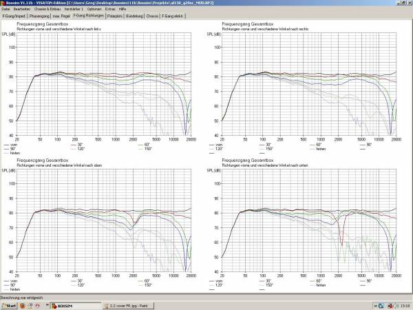
Id love some feedback concerning which design is better, especially regarding the phase and power response/off axis behavior, If anyone would like to help.
Ill post some plots and hopefully i can get some constructive criticism on either or both, in order to help me choose which crossover to employ before i finish building the speakers.
My current speaker project is going well. I had finalised my crossover design until i messed with Boxsim some more, and came up with an alternative design.
Id love some feedback concerning which design is better, especially regarding the phase and power response/off axis behavior, If anyone would like to help.
Ill post some plots and hopefully i can get some constructive criticism on either or both, in order to help me choose which crossover to employ before i finish building the speakers.
Once again thanks, and I hope i can get some experts to help with evaluation
So once again thanks. basically id like some help evaluating the merits of both designs, and criticisms also, so i can choose which crossover to use in the finished design.
All Opinions welcome, it is a 2 way system in both cases
One is a 2nd order HP and 2nd order LP
One is a 2nd order LP and 1st order BP
If you want to be really impressive (or are really bored), then guess which is which!
Otherwise, ALL opinions welcome (no full range comments thats the next project
So once again thanks. basically id like some help evaluating the merits of both designs, and criticisms also, so i can choose which crossover to use in the finished design.
All Opinions welcome, it is a 2 way system in both cases
One is a 2nd order HP and 2nd order LP
One is a 2nd order LP and 1st order BP
If you want to be really impressive (or are really bored), then guess which is which!
Otherwise, ALL opinions welcome (no full range comments
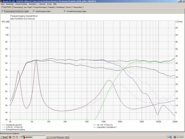
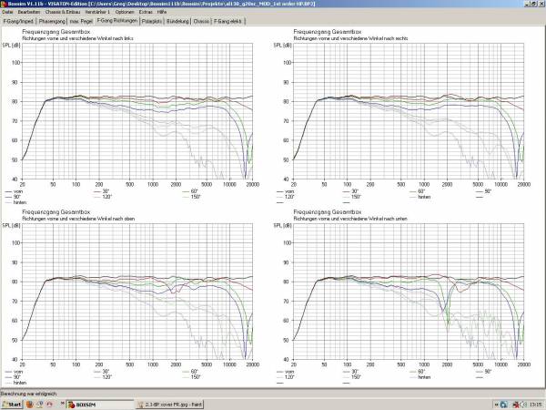
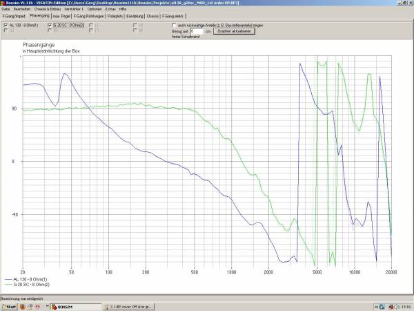
thats the next projectWho's to say they'd sound much different? The phase angle plots seem most interesting, though I find they can be hard to interpret if they fold up and down a lot as the second seems to do. I don't know if the LF differences are audible and the HF differences aren't that great. I'd go with the first (original) design.
The phase angle plots seem most interesting
I agree. The Phase behaviour of the 2nd crossover doesnt look to be as good as the 1st, to me at least. The differences in FR are much less obvious.
Anyone have anything else to add?
1st order at 2.4k - is a bad idea for tweeter, unless you have some really big tweeter, that thinks it is midrange...
I would say the same thing. You notice the neck at 2K on tweeter from Fs.haha youre right...i had neglected to notice the turnover frequency.....since the tweeter is Fs at about 1800Hz i think it is definitely a bad idea...
Last edited:
lol yes i notice...now i ACTUALLY look at the plots......So the first crossover is better then?
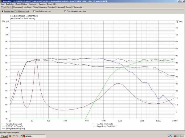
The crossover point is slightly lower since the cap on the HP was increased from 5uF to 6uF, and i was worried about that turnover point being a little too low aswell.
this changes the -3dB turnover from 3k to 2.7k, and the tweeters Fs is 1.8k, so im a bit worried im cutting it a bit fine. I honestly cant hear any distortion or ill effects though, although it is early stages and i have only liostened to the crossover in the lower xover point for a few hours
Last edited:
Good that you're using the software
It must be said, that it's an incredibly flat simmed response. My speakers are nowhere near that... Still, it's sound is a different matter.
I'd agree that the first crossover is better, but for other reasons...
First thing I noticed - the woofer is contributing less further up, meaning there's a lower chance you'll hear the inevitable break-up from the aluminium cone.
The response also looks a little smoother over the cross-over region.
The phase on the first one has a similar curve for both woofer and tweeter, so you won't have any problems with cancellation.
Hope it all goes well
Chris
Let's see if he can live with that... (nasty and it's still there.)First thing I noticed - the woofer is contributing less further up, meaning there's a lower chance you'll hear the inevitable break-up from the aluminium cone.
mondogenerator, did you give the final dimensions, on the software, for the speakers, location of port, and the front baffle dimensions and drivers positions?
Last edited:
It must be said, that it's an incredibly flat simmed response. My speakers are nowhere near that... Still, it's sound is a different matter.....
It is impressively flat, only downside is that the smoothing is 12th octave (i think), and also that i offset the tweeter to reduce the baffle ripple above 5k. However i neglected to measure, and realised my offset is impractical...
When reset to centre position the response is still within +/- 2db though, so i may use a smaller offset, and live with the small ripple. After all im planning to use felt on the baffle around the tweeter to 'blur' the baffle edges a little, and i think this will help with the ripple also.
Soundwise, I am impressed with the test box i have been using for several months, and the crossover that is shown here. it sounds balanced and no unwanted emphases. If i were to pick fault with any of it, i would say that i could perhaps do with 1 MAYBE 2dB less BSC, but I think its to be expected since i have the boxes about 3" from the rear wall, and i really should change that!
....The response also looks a little smoother over the cross-over region.
The phase on the first one has a similar curve for both woofer and tweeter, so you won't have any problems with cancellation.
Hope it all goes well
Chris
Thats exactly my take on the phase response, since the tweeter is not reverse phased it surprises me a little since im used to butterworth curves and the hump or dip thats produced, depending on driver phasing
Let's see if he can live with that... (nasty and it's still there.)
lol yes the breakup never goes away, however, with the notch i added to the crossover, combined with the LP rolloff, it is attenuated some 25-30dB depending on where you take the measure, so im fairly happy it wont mar the result until i get to 100dBs. And to be fair i doubt i will since the design is only about 84dB/W and i have a 30W amp..
mondogenerator, did you give the final dimensions, on the software, for the speakers, location of port, and the front baffle dimensions and drivers positions?
Yes. I used the final driver positions, baffle dimension, bevel on Boxsim to calculate the results. However my german isnt all that great and I am not sure how to input the port position, or indeed IF you can. There are a wealth of options which i still dont understand, even after Chris's Boxsim Tutorial. Which was great, and further than i could get alone. If i could read german fluently, then im sure there are many more things i could include to improve the sim.
Last edited:
Foil inductors are superior to wire coil type. I recommend that you bypass any electrolytic capacitors you use with polystyrene, polypropylene or mica caps, unless you want to use non-electrolytics.
Foil inductors are superior IF you think that 'skin effect' is something to worry about in a LP filter, or are after super low DCR. In my application 1mm ferrite cored inductors are perfectly adequate, and the 12 gauge Alphacore foils i have showed no audible difference.
As for caps....well i have not/would not use electrolytics anyway---unless forced by situation...i.e. midrange BP
All caps are polyester film/polypropylene film 1000V rated or above
Foil inductors are superior to wire coil type.
I have never seen actually data that proved this. Could you point out the link for these conclusions?
You can use this translation (1, 2) for Port location, front or back, on the dimensions menu. And (3) for tweeter (closed back driver, I think), on the drivers menu. German is not my language....I used the final driver positions, baffle dimension, bevel on Boxsim to calculate the results. However my german isnt all that great and I am not sure how to input the port position, or indeed IF you can. There are a wealth of options which i still dont understand, even after Chris's Boxsim Tutorial. Which was great, and further than i could get alone. If i could read german fluently, then im sure there are many more things i could include to improve the sim.
Attachments

Last edited:
- Status
- This old topic is closed. If you want to reopen this topic, contact a moderator using the "Report Post" button.
- Home
- Loudspeakers
- Multi-Way
- Which crossover is better?