 My D-500 broken long time ago. At recent I decided to open the cover to check out. Unfortunately, when I screw off Audio PCB the connect cable of Digital PCB was broken. When I pulled out flat cable (AWM 2896) I found connect points peel off. Therefore, I went to electronic shop bought new flat cable to replace. Here come problems:
The new flat cable spec seems won't fit slot on Digital PCB. Need cut off the edge of cable. The Audio PCB doesn't have a slot like Digital PCB. It's soldering by manual. So I have to cutted cable in half and peel off each isolation. When I insert cable to slot and use Digital Multi-Meter to check every point of connector on Digital PCB is link to peel of side. A new problem rise-up!
 My Multi-Meter shows short ciucuit between 2 points. Means if I manual soldering cable on Audio PCB will cause big disaster if I turn on power.
I pulled off cable and compare to previous cable found the gap of connect point are differences in between. So, that's why short circuit happen.
Now, I need to figure out the circuit between Digital PCB (Connect P106)
An externally hosted image should be here but it was not working when we last tested it.
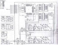
and J1(On Audio PCB) An externally hosted image should be here but it was not working when we last tested it.
Maybe just simple drawing to helping me. At least I won't solder wrong connection.  I would be appreciate anyone who can help me.
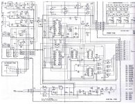
- Status
- This old topic is closed. If you want to reopen this topic, contact a moderator using the "Report Post" button.