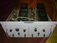
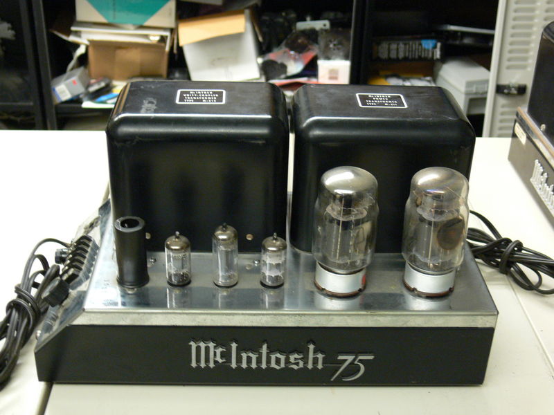
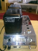
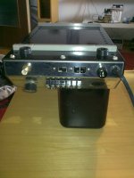
In short, I got this from a friend. It looks like commercial product that uses two massive (OEM?) McIntosh amplifiers. It's really heavy ")
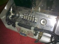
The tubes are 12AU7, 12AX7, 12BH7, 12AT7 and two KT88. The input is BNC and the print next to the potentiometer (with switch) reads "2.0V setting for McIntosh preamp. There is a speaker output-strip with labels "GND,COM,4,8,16". There is also an output-socket that seems to be feeding some higher-impedance loads.
I can make more pics tomorrow. Can anyone identify this beast?
Could the amplifiers be operated @ 240VAC 50Hz with a sufficiently large step-down transformer or would the 50Hz cause trouble (less efficiency)?
Attachments
I do not think it was uncommon for them to be used for non-audio applications. The one I showed above was from a collection we had in a University engineering department. They were used, in our case, as small shaker amplifiers for vibrations testing.
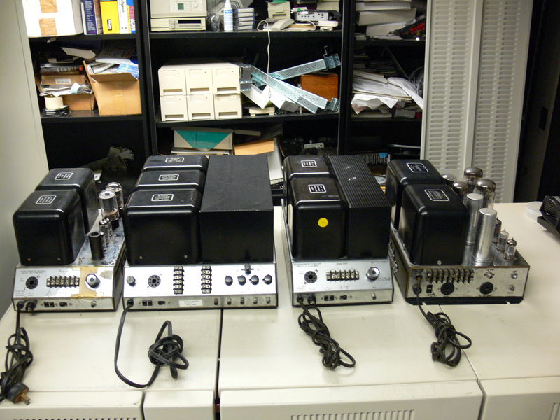
(An MC 40, 60, 75 and 275, not in the order pictured)
(An MC 40, 60, 75 and 275, not in the order pictured)
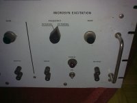
I'll venture a guess and say that's some sort of instrumentation, with a pair of MC75 based amps in it. The MC75 schematic is here.
McIntosh did not skimp on "iron". I don't think you need worry about 50 Hz. mains. Buy a pair of Allied 6K175VCP or equivalent 2000 VA step down autoformers. "Mac" circuitry is Class "B" and you don't want adverse regulation effects in the autoformer. Thank Kevin K. for that tip.
The "iron" in your possession is GOLDEN. Do a full stem to stern refurb with modern parts. Then play those monoblocks regularly. You will be smiling.
That's quite a find and I'm jealous.
This is from the estate of the late husband of a friend's kindergarten nanny who called him up to clear his garage after 40 years of hoarding...we spent the whole day there assessing the vast of his collection. Mind boggling. We'll be back in two week with a van. I remember a 1.5kVA step-down transformer that'd go nicely with the twins...
This is from the estate of the late husband of a friend's kindergarten nanny who called him up to clear his garage after 40 years of hoarding...we spent the whole day there assessing the vast of his collection. Mind boggling. We'll be back in two week with a van. I remember a 1.5kVA step-down transformer that'd go nicely with the twins...
For best performance you are going to want a much bigger auto-transformer than the 1.5kVa unit you reference. In this case larger is better, and two separate units in the 1 - 2kVa range isn't inappropriate if you have the space. A single larger unit remotely located is just fine as well.
Very lucky find, these are great driving some fairly difficult loads, planar magnetic and electro-static speakers coming immediately to mind.
Be sure to allow for adequate ventilation. Check the bias supply and coupling caps before proceeding. (Electrolytics generally should all be replaced.)
Yup, those Mac amps used to show up surplus from vibration and shaker table use. Don't be shocked when you find out what they're worth.
CH
$$$$
Rodeodave you might want to keep that to yourself until you actually have them..
The red carpet in the pictures is in my living room so I already have the twins at home
And I was quite shocked to see what they are worth.
About the autotransformer...as far as I remember the transformer I'm referring to had two separate windings on one massive core (it had 20-30kg I'd say). So it should be an isolation step-down transformer and I suppose that in that case the full power rating should be applicable.
P.S.: Haha, so many typos, even in the title. But what can you expect at 3AM...
Yup, those Mac amps used to show up surplus from vibration and shaker table use. Don't be shocked when you find out what they're worth.
CH
The department sold them a couple of years ago. They were sold as is, untested and had sat for about 20 years without use. They brought a good price and I think everyone was happy, buyers and seller. A friend of mine ended up buying the MC-275 and it is his pride and joy.
you lucky bstrd !
considering that you have two of them , just wire their mains in series ( taking care of phase ) and plug them in 220V wall outlet .
you owe me a beer ; now you can use autoformer for something else

edit:
you are sure that mains xformers aren't multitap ones ?
considering that you have two of them , just wire their mains in series ( taking care of phase ) and plug them in 220V wall outlet .
you owe me a beer ; now you can use autoformer for something else
edit:
you are sure that mains xformers aren't multitap ones ?
you lucky bstrd !
considering that you have two of them , just wire their mains in series ( taking care of phase ) and plug them in 220V wall outlet .
you owe me a beer ; now you can use autoformer for something else
edit:
you are sure that mains xformers aren't multitap ones ?
Zen, you've given consistently good to great advice, until now that is..
These amplifiers run near class B and their power consumption varies significantly with the signal level applied, given that they are also two separate amplifiers with their individual component tolerances there is no way to assure that the voltage delivered to each amplifier is consistent in a series connection. VERY BAD IDEA!!!
A few McIntosh power transformers may have had 230V windings, but on American Hi-Fi equipment this is comparatively rare and for export only. These probably do not...
......until now that is..
......
aaargh !
mea culpa

sometimes I must remind my self to think outside A class boundaries ........
anyway - certainly not last time that ZM act as dumbest dumb

tnx for correcting me ........ seems that I owe a beer now

aaargh !
mea culpa
sometimes I must remind my self to think outside A class boundaries ........
anyway - certainly not last time that ZM act as dumbest dumb
tnx for correcting me ........ seems that I owe a beer now
Yep you owe me a virtual beer..
...just wire their mains in series...
Funny, someone else gave the same advice on the same topic: http://www.diyaudio.com/forums/tube...olt-mcintosh-mc275-230volt-2.html#post2110971
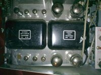
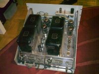
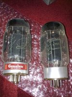
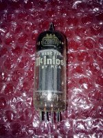
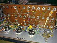
I found time to pull them from the 19'' unit and clean them a bit. Found some nice tubes
The insides look clean, despite the usual elektrolytics leaking.
Now I have like a hundred questions planning the restauration:
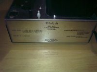
1) Any chance to link the serial number to a production date?
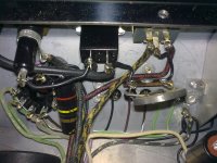
2) The circuit's ground is directly connected to the chassis at the input (see picture) and the chassis is supposed to be connected to earth-ground. Can the connection circuit_gnd -> (chassis=earth) be made with a thermistor? This is common practice in (Pass inspired) solid state amplifiers (see f.e. http://www.firstwatt.com/downloads/F3-service-manual-sm.pdf).
3) Does the circuit's ground connect to the chassis somewhere else? I've already noticed that it does so at the input as the BNC-socket is not insulated.
4) How is the earth connection usually made? My units' power cords just have two wires. Maybe the rack the unit was once mounted in had an earth-connection.
5) How do people usually fit a switch? Or just use a switchable outlet strip?
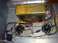
6) The thermistor in series with the primary...it must go. Any info on a suitable replacement? The cold value apparently is ">25R" but what about current and hot value?
7) Any recommendation regarding what to replace the selen rectifiers with? Just any big fat diode that fits the bill?
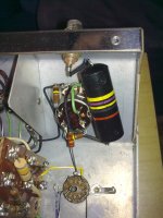
8) I'll most certainly replace all the electrolytics. Any info on where to source them? Is it worth using film caps at the output tubes' kathodes (12uF250V)? I'll also replace the film caps.
9) Any info on the inductors at the output tubes' anodes? Ah, just seen it, 2.2uH (found in the manual from Antonio Ceretti American Vintage Audio Equipment). Should I replace them too?
10) Why is the circuit AC-coupled? Can I omit the switch/pot?
11) According to the schematic notes in the service information (again found at Antonio Ceretti American Vintage Audio Equipment) most of the resistors are rated at 1/2 W. Would you replace these resistors (1W MOX?)? What about the higher power ones? They seem to be 220R/5W wirewound. Should I replace them with MOX types?
Thank you for your help, guys. Now some pictures.
Attachments
-
 150320101382.jpg554.3 KB · Views: 208
 -
 150320101373.jpg723.3 KB · Views: 201
 -
 150320101365.jpg900.4 KB · Views: 211
 -
 150320101383.jpg479 KB · Views: 202
 -
 150320101393.jpg451.6 KB · Views: 184
 -
 150320101396.jpg573 KB · Views: 108
 -
 150320101397.jpg526.7 KB · Views: 99
 -
 150320101425.jpg620.5 KB · Views: 225
 -
 150320101424.jpg599.5 KB · Views: 198
- Status
- This old topic is closed. If you want to reopen this topic, contact a moderator using the "Report Post" button.
- Home
- Amplifiers
- Tubes / Valves
- Pleas help identify this McIntosh valve amplifier