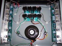
 Well, my DIY F1 seems to measure as it should but the output is very weak. With my 24v Aikido preamp i can barely get any sound out of my C&C Abbys. 3/4 on the volume and just barely anything. Full volume and distortion sets in but it doesnt get any louder. Zero bass, but nice soundstage would be the best way to describe it. I've measured just about everything i know of and the values are as follows...and were taken after 1 hour warm-up...
Source Drain Gate
L Q1 3.77 13.77 8.15
R Q1 3.75 13.77 8.13
L Q2 3.78 13.82 8.15
R Q2 3.76 13.81 8.15
L Q3 21.85 13.82 17.30
R Q3 21.91 13.82 17.30
L Q4 21.84 13.91 17.20
R Q4 21.90 13.89 17.30
L Q7 .094 2.82 5.00
R Q7 .087 2.82 5.01
Voltage across R27-R30
L R27= .577, L R28= .577, L R29=.573, L R30=.576
R R27= .571, R R28= .572, R R29=.572, R R30=.570
The differential DC offset measured across the speaker terminals
Left 45mV (with load) 60mV (NO Load)
Right 25mV (with load) 35mV (NO Load)
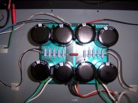
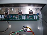
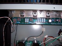
I've attached some pictures for reference , maybe you folks can see something I'm missing ...?
Thanks in advance for any help.
Regards, Daniel.
Attachments
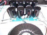
I'm not sure that a good insight, but if the reverse polarity protection zener would be present.
Not on the board in relation to drawing, but the original wiring diagrams for comparison.
Maybe.
Gyuri
PS:
Of course, it would be better if the bottom could be seen.
Not on the board in relation to drawing, but the original wiring diagrams for comparison.
Maybe.
Gyuri
PS:
Of course, it would be better if the bottom could be seen.
Last edited:
Bad solderings could be a cause of your problem.
Apart from that, a signal tracer can be made with very simple tools.
If you have a signal generator, you can inject a 1kHz into the input and follow the signal path with your multimeter in AC mode.
Else, internet or a kind fellow member can provide you with a simple sine wave, playable from your PC.
I think it was not a bad idea, but I found this photograph, this is not the problem.
I'm sorry.
Perhaps there is someone better idea.
Papa Pass help us!
And besides, your name included in our daily prayers.
http://www.diyaudio.com/forums/group-buys/158838-f1-amplifier-psu-pcbs-free.html
Wacky Gyuri
PS:
And those diodes really zener diodes?
I'm sorry.
Perhaps there is someone better idea.
Papa Pass help us!
And besides, your name included in our daily prayers.
http://www.diyaudio.com/forums/group-buys/158838-f1-amplifier-psu-pcbs-free.html
Wacky Gyuri
PS:
And those diodes really zener diodes?
Last edited:
.... No scope unfortunately, just a Fluke 179 multimeter....
Regards, Daniel.
Does that Multimeter do AC volts. You can use that to trace the signal
I can bet that you feed it with unbalanced signal , and that you forgot to ground minus leg input
.
Hmmmm...
Gyuri, as chance would have it i did originally install the zeners backwards but the guys caught that in my other thread so they have been re-soldered correctly. Part is a 20v 1w 5% Diode Zener from Digi-key.
Zen Mod, I am indeed feeding unbalanced inputs but if you take a look at one of the pictures i posted you will see a small "red coated" copper jumper that i am using on the board to tie the ground and negative balanced input section on board together. (I think this is correct?) The input area of the board is mislabeled a bit but i was able to trace that before i started soldering.
flg, the multimeter does do AC volts. How would i use the multimeter to trace the signal. I'll measure the resistors you mentioned but what values would i be looking for ?
Netlist, can you expand a bit on your idea ? This is all a first for me so very little experience with electronics.
Tea Bag, just checked the speaker binding posts and no problems with grounding there.
Here's a very basic question. Can anyone verbally trace the grounding path for me ?
Thanks everybody, please keep the ideas coming.
Regards, Daniel.
Bingo !
Thank you Mr. Pass and flg for getting me to look more closely at the resistors. I started comparing the schematic from the owners manual for the f1 with the BOM posted somewhere here on DIY Audio, and the parts list that I ordered. The BOM has a mistake for R7-8 as it lists 392ohms instead of Kohms. Also I ordered R5-6 incorrectly as 562ohms instead of Kohms. Now I feel like the village idiot...did I mention that i hate de-soldering ?
I'll post an update when i get the correct values ordered and installed. Thanks again for the help.
Regards, Daniel.

Its Alive !!!
After a bit of desoldering and resoldering in the correct value resistors I now have a functioning F1. Paired with a DIY 24V Aikido and my C&C Abbys it sounds wonderful... huge bass and very revealing. Thanks to everyone for helping me get her up and running, and a big thank you to Mr. Pass for sharing.
Regards, Daniel.
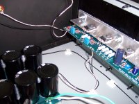
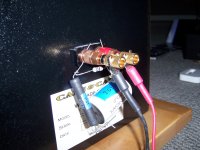
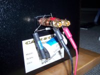
Impedance
Thanks for the reminder NP. Been playing with it today and it definitely makes a difference. I did find after a little experimentation that the quality of the cap seemed important . Luckily i had a couple of unused Sonicaps laying around that just happened to be the right value. Does this look about right ?
Daniel
Attachments
- Status
- This old topic is closed. If you want to reopen this topic, contact a moderator using the "Report Post" button.
- Home
- Amplifiers
- Pass Labs
- Trouble Shooting an F1