I bought a 500mA Class A (+/-)Shunt Reg Kit from eBay Hong Kong, for use with an RIAA circuit I built.
The RIAA requires 2x 27v DC and pulls about 20-30mA per channel.
I can't get the shunt reg to work as I'd hoped. I have a toroidal with 18v secondaries, as recommended for the kit, and when I wire it up I get 13.7v DC per side. When I use it bipolar, of course, I get 27.4vDC, very close to my desired voltage, but I also get some small voltage fluctuations, and I can't get more than 1 volt difference with the whole range of the pots, so I don't think that's ideal at all.
I'm not sure if it is regulating properly, as I had thought I would be able to tune the voltage with the pots, and I expected absolute voltage stability.
If anybody can advise me, I would be most grateful. Here's the schematic:
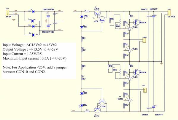
Last edited:
I still can't see the image. You could attach an image to the post if you don't want to rely on the site where the image is hosted.
You should probably describe the psu before the reg, bridge, CRC filter, what value C, R, and C, etc.
Edit: probably something wrong with the site that the diyaudio attachments uses.
You should probably describe the psu before the reg, bridge, CRC filter, what value C, R, and C, etc.
Edit: probably something wrong with the site that the diyaudio attachments uses.
Last edited:
OK that makes sense. Thanks to you all.
I wasn't sure if I could get the full range of voltages out of an 18v transformer, as I've never built a shunt reg before.
I tried with the jumper leads in, and it seems I can go up to about 24v DC before the lights start flickering and then go out. Without the jumper leads I get 27v DC and no lights and it's impossible to tune the voltage by more than +/- 1volt.
I'll get a 40v traffo then. Many thanks, Lucas
There were twin secondaries - 0-18, 0-18, not the centre tapped 18-0-18 I joined together like this 0-18 + 0-18 making 0-36. The phasing issue is possible, I guess, but it seems smooth and solid in terms of voltage output, and the power supply is outputting 27volts solid as a rock, as it should.
Is it dangerous to do this series wiring of the two secondaries? Or not recommended for any other reason? I guess I am halving the VA rating, but that is still within my requirements for the RIAA.
Many thanks
Lucas
Is it dangerous to do this series wiring of the two secondaries? Or not recommended for any other reason? I guess I am halving the VA rating, but that is still within my requirements for the RIAA.
Many thanks
Lucas
So do you have the point where you joined the secondaries together connected to ground? Can you draw what you have done as I can't see how you are getting plus and minus 27V from the regulator output if you have wired it as per the supplied drawing - 18V rectified produces an absolute max theoretically possible of only 25V, and that's ignoring any losses.
Last edited:
Oh jeez. If I connected the joint to ground it would short my house fuses out.
An 18v x2 traffo can be used in 3 ways that I know of. The first is to power two rectifiers with 18v AC each, or a single rectifier with 18v AC with twice the rating, by wiring the two secondaries in parallel.
I am using it in the third way I now know of, which is in series, so I take the first 18v through the second, adding up to 36v. I haven't done it before, but it works. I was asking if there was a reason I shouldn't do this, as I'm no expert, but the connection should most definitely not be earthed, as this will short quite massively and trip my house RCD.
It's not a centre-tapped transformer. Not 18-0-18!!!
It is 18-0 and 18-0. What I have done is like putting two 12v batteries together to get 24v, but with AC. I haven't done it before, so I wasn't sure, but it seems to work. It definitely outputs 40v AC anyway.
Does that make more sense?
Lucas.
A schematic of what you are doing would clear up confusion.
Remember there are a lot of beginners here and it is very difficult to judge skill level on the forum. If I understand your question, a pair of 18V windings can be used separately, as an 18-0-18V or a 36V winding. Since you have plus and minus supplies in your posted regulator, if you use both windings on the positive, you will require an additional transformer for the negative supply.
HTH
Doug
Last edited:
no you don't.You need around 40-42V AC on the transformer secondaries , to get 27V DC with your shunt
25Vac will just about work for a 27Vdc regulated supply.
Upto 30Vac could be used if the input (CCS) transistor can take the extra dissipation.
I understand what you are saying Lucas, but it does not fit with what is happening. That is why we are wanting you to trace what you have really done and draw it. Just putting 36V in to the whole regulator theoretically cannot give you 54V in total out. 1.414 * 36 = 51V and then losses come into play.
If you have wired things correctly it is entirely safe for you to ground the PSU as shown in the schematic.
If you have wired things correctly it is entirely safe for you to ground the PSU as shown in the schematic.
- Status
- This old topic is closed. If you want to reopen this topic, contact a moderator using the "Report Post" button.
- Home
- Amplifiers
- Power Supplies
- Shunt Regulator Issues/ Questions