This is a receiver tube (heptode + triode) so you're mostlikely to find it used in some sort of radio receiver, serving in RF portion of the circuit, which is irrelevant for your project.
However that doesn't mean we cannot come up with a schematic for you to try") We do need some details first:
We do need some details first:
1: What is your B+ voltage ?
2: What kind of load (= input impedance of the amplifier) do you intend to drive with this preamplifier ?
3: Which audio source is going to end up feeding this preamplifier ?
4: What voltage amplification factor are you looking for ?
However that doesn't mean we cannot come up with a schematic for you to try
We do need some details first:1: What is your B+ voltage ?
2: What kind of load (= input impedance of the amplifier) do you intend to drive with this preamplifier ?
3: Which audio source is going to end up feeding this preamplifier ?
4: What voltage amplification factor are you looking for ?
Looks very difficult to me; the triode curves are a disaster, (but maybe they sound good for a guitar-effect), it has an amplification of only 10x, and the plate resistance is .5 MegaOhm. Maybe you can do something cool with the heptode...
If you want to drive 4 or 8 ohms you'll need a poweramplifier; this tube will never be able to drive a speaker.(or i'm missing something)
If you want to drive 4 or 8 ohms you'll need a poweramplifier; this tube will never be able to drive a speaker.(or i'm missing something)
The b+ voltge is going t be 12 volts and the load is going to be 4 to 8 ohms. The input is most likely a guitar as I do not want do destroy any iPods or anything by accident.
Ugh, let's clear up your misconceptions first:
First of all, as pauldune has already told you, there is no way you will drive 4R/8R load and get anything useful out of it, unless you are into microwatts
You can cobble together a preamplifier though.Second, why on earth would you destroy your iPod by using it as the signal source ?
It would take something really stupid (like deliberately shorting its output) in order to destroy it. Third, is B+ set in stone or do you have some leeway in designing your power supply ? I would opt for 17-18V DC if I were you because that would allow you to (A) run heater off of CCS (using a simple LM317 regulator wired as a current source) and (B) use active anode load (using JFETs) in order to get the maximum swing out of your tube. This would give you more flexibility and allow you to use more feedback (if desired) to compensate somewhat for inherent nonlinearity of low voltage operation, plus you could use cathode bias with correspondingly lower value of grid resistor (= lower input sensitivity to hum).
Ultimately, preamp is expected to provide different things in different roles - with guitar you might appreciate any distortion it can generate, with audio (music) you will mostlikely want faithful reproduction instead.
@pauldune: could you please point me to the datasheet showing the characteristic curves ? All I can find are limiting values
Ugh, let's clear up your misconceptions first:
@pauldune: could you please point me to the datasheet showing the characteristic curves ? All I can find are limiting values
http://www.classiccmp.org/rtellason/tubedata/12FX8.pdf
ya actualy a distortion pedal or boost would soun great on my current guitaramp. i am very new to tubes so thanks for the help. i also have a 6av5ga power tube laying around so i might be able to make a poweramp with that.Looks very difficult to me; the triode curves are a disaster, (but maybe they sound good for a guitar-effect), it has an amplification of only 10x, and the plate resistance is .5 MegaOhm. Maybe you can do something cool with the heptode...
If you want to drive 4 or 8 ohms you'll need a poweramplifier; this tube will never be able to drive a speaker.(or i'm missing something)
on sopht amps sight, they say the 12k5 can put out 1/4 watt.
1/4 watt but not for very long judging by the datasheet. It claims 0.035 watts typical. Maybe a pair in push pull...
http://www.mif.pg.gda.pl/homepages/frank/sheets/137/1/12K5.pdf
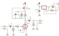
I had a close look at the 12FX8 datasheet ... Man is this one irritatingly tough nut to crack or what ? The easiest way to use it is with grid leak bias afterall, due to its internal heater-cathode connection.
Anyhow, if I had one of these tubes and wanted to give it a try, this is how I would go about it (see attached pic).
Value of R2 must be determined experimentally as there is way to much variation allowed by the datasheet. How to determine its value ? Hook it up to a power supply (capable of supplying at least 5V) as shown. You can omit RP6 and C3. Hook a miliamperemeter between JFET source and supply ground. Adjust value of R2 until current measures no more than 1.3 mA. Note the value and pick RP6 approximately 5 times the size of R2.
RP6 may be omitted if you don't feel like tweaking anode load current (I'd omit it for initial testing, then put it in in order to tweak the sound once everything is working). C4 accidentally says 0.1 uF, should be 1 uF but isn't critical because both reference and load are resistive and voltages across them stable.
You can use 2 PP3 (9V) batteries in series for tinkering if you don't have an 18V power supply handy. A standard battery will give you 1-2 hours of operation with vast majority of power wasted on heating.
Remember to hook unused heptode terminals to the ground through large (1M-10M) resistors so some negative bias can develop and grid current will not flow.
The easiest way to use it is with grid leak bias afterall, due to its internal heater-cathode connection. Anyhow, if I had one of these tubes and wanted to give it a try, this is how I would go about it (see attached pic).
Value of R2 must be determined experimentally as there is way to much variation allowed by the datasheet. How to determine its value ? Hook it up to a power supply (capable of supplying at least 5V) as shown. You can omit RP6 and C3. Hook a miliamperemeter between JFET source and supply ground. Adjust value of R2 until current measures no more than 1.3 mA. Note the value and pick RP6 approximately 5 times the size of R2.
RP6 may be omitted if you don't feel like tweaking anode load current (I'd omit it for initial testing, then put it in in order to tweak the sound once everything is working). C4 accidentally says 0.1 uF, should be 1 uF but isn't critical because both reference and load are resistive and voltages across them stable.
You can use 2 PP3 (9V) batteries in series for tinkering if you don't have an 18V power supply handy. A standard battery will give you 1-2 hours of operation with vast majority of power wasted on heating.
Remember to hook unused heptode terminals to the ground through large (1M-10M) resistors so some negative bias can develop and grid current will not flow.
Attachments
- Status
- This old topic is closed. If you want to reopen this topic, contact a moderator using the "Report Post" button.
- Home
- Amplifiers
- Tubes / Valves
- space charge 12fx8 amp or preamp schematic?