I got side-tracked again, my trusty old NAD reciever in my office myst be getting jelous of all the orange lights and tried to do the same. So, new project on the list. I can get buy with a passive preamp (adding a switch inside my amp) but I need FM.
I have an old Eico tuner. It has a multiplex output, but I have not seen a schematic for an external stereo decoder in 40 years. It is still a solid and stable tuner. It would be fun if I could do a refurb and get stereo out of it. Any ideas? I could just run it mono, as I listen to CDs or NPR on the radio.
If I do find need of a buffer stage. Of the hundreds of preamp designs out there, any current thinking on a gain of 2 or 4 line stage? Clean would be the order of the day. I have an old Telematic amp I could recycle as an active preamp.
Your wish is my command. 
DIYer extraordinaire Steve Bench has provided us with a multiplex decoder design. Mr. Bench's schematic is uploaded.
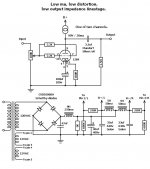
The 12B4 makes for a very nice low gain line stage. If you are interested in the design I've uploaded, suitable low cost power "iron" can be obtained from Allied.
DIYer extraordinaire Steve Bench has provided us with a multiplex decoder design. Mr. Bench's schematic is uploaded.
The 12B4 makes for a very nice low gain line stage. If you are interested in the design I've uploaded, suitable low cost power "iron" can be obtained from Allied.
Attachments
Super. 2 for 2. I should be able to stuff the decoder inside the eico.
I forgot about Allied. Need to look up that tube. I am new to tubes and have not seen this pin3 connection drawn like this. That is the whole point, to learn. If I just wanted music, I'd buy a radio!
Lots of CCS's out there, any recomended preference for this one?
I forgot about Allied. Need to look up that tube. I am new to tubes and have not seen this pin3 connection drawn like this. That is the whole point, to learn. If I just wanted music, I'd buy a radio!
Lots of CCS's out there, any recomended preference for this one?
I have to admit, looked several times. I don't understand what the DC bias on the filament is for. The cathode should only be at about 10V, so not a problem there.
I am also totally baffled on the two leads to the grid. My books are still on their way from Amazon. Not a standard triode somehow I guess.
I am also totally baffled on the two leads to the grid. My books are still on their way from Amazon. Not a standard triode somehow I guess.
Lots of CCS's out there, any recomended preference for this one?
If the load is very easy, like typical tubed gear, an IXYS 10M45S will do the job.
OTOH, if your are going to drive something resembling the IHF "standard" of 10 KOhms, which is nasty, something cascoded is in order.
Look at the schematic again, carefully. You will see that the CT of the 12B4's heater is biased off B+ and grounded via a capacitor. That arrangement reduces the hum level. The 12B4 data sheet is here.
Allied stock # 967-2438 takes care of the 2X "12" VAC windings to energize the 12B4 heaters. Allied stock # 967-9502 will energize the B+ rectifier bridge.
BTW, you don't have to use the expensive "boutique" parts shown in the drawing. The fellow who made that drawing, from a narrative I provided, loves that stuff. Excellent results can be obtained at a much more rational price. For instance, a 3.3 μF. Solen MPP part bypassed by a 330 nF 716P series Orange Drop is plenty good in the O/P coupling cap. position.
Reduces the hum. Had to be but I don't understand how. Definitely worth a shot to try if this allows AC filaments and low noise. Sometime ago I was told running DC filaments shortened their life. Others say by current regulating them with DC, you increase their life.
So much to learn. It seems tubes are quite responsive to execution. For easilly (cheap) parts, some amount of readjusting the power supply is in order. Allide has 6H 200Ma chokes, so maybe a single pi for each tube with larger bleed resistors and larger caps would match the performance at reasonable cost if the primary can take it.
All this fast diode stuff is new. Reducing switching time will reduce the heat disapated, but I have a hard time believing it has any effect with that much filtering. Could be wrong, but I am sure they can't hurt. Is it because they are cheaper than small low ESR bypass caps right across the diodes like we used to do?
Reduces the hum. Had to be but I don't understand how. Definitely worth a shot to try if this allows AC filaments and low noise. Sometime ago I was told running DC filaments shortened their life. Others say by current regulating them with DC, you increase their life.
So much to learn. It seems tubes are quite responsive to execution. For easilly (cheap) parts, some amount of readjusting the power supply is in order. Allide has 6H 200Ma chokes, so maybe a single pi for each tube with larger bleed resistors and larger caps would match the performance at reasonable cost if the primary can take it.
All this fast diode stuff is new. Reducing switching time will reduce the heat disapated, but I have a hard time believing it has any effect with that much filtering. Could be wrong, but I am sure they can't hurt. Is it because they are cheaper than small low ESR bypass caps right across the diodes like we used to do?
The hot wire (heater) inside the cathode sleeve emits some thermionic electrons. That emission varies in step with the mains freq. Biasing the heater positive, with respect to the cathode, causes the filamentary thermionic electrons to be attracted back to the wire. Bada bing, bada bang, bada boom, hum level is reduced!
ALL PN junction diodes exhibit a reverse recovery spike, that's a consequence of minority carrier injection. Being majority carrier only devices, Schottky diodes (like those shown in the drawing) don't exhibit a reverse recovery spike. It's better to avoid generating switching noise, from the beginning, than it it is to snub it, after the fact.
The PSU shown in the drawing employs a pseudo-choke I/P filter. That small "fudge factor" part does 2 jobs: it tweaks the rail voltage upward and it protects the SS diodes from inductive kick back spikes. The actual value of the tweaking cap. has to be determined by experimentation, at the bench. The B+ rail needs to be > 120 V. and less than 125 V. Make the "fudge factor" part too large and the PSU will exhibit cap. I/P behavior.
The bleeder resistor is sized to ensure that the critical current essential to choke I/P behavior is drawn. Choke I/P filters are well regulated. Dig up an old edition of the ARRL handbook. You will find that LCLC is proper for a supply that is both well regulated and low ripple.Oh yeah, a reasonable approximation to the critical current (in mA.) is given by V/L. It works out that 1 KOhm of resistance is needed for each Henry of the 1st inductor, in the bleeder resistor wired in parallel with the 1st filter capacitor.
The hot wire (heater) inside the cathode sleeve emits some thermionic electrons. That emission varies in step with the mains freq. Biasing the heater positive, with respect to the cathode, causes the filamentary thermionic electrons to be attracted back to the wire.
Good explanation. I've known in the back of my mind that elevated heaters reduced hum, but I never bother to ask why. Now I know. On a related topic, the cathode sleeve must be emitting electrons from its inside as well as its outside. Does the elevated heater voltage attract the inside cathode electrons as well? Of course, it must. Does this mean that is H-K current drawn? What's a typical draw, in mA? I'll assume it is pointless to concern myself with heater dissipation caused by this effect, but perhaps TOO great of a potential applied to the heater might cause it to run much hotter than designed?
On a related topic, the cathode sleeve must be emitting electrons from its inside as well as its outside. Does the elevated heater voltage attract the inside cathode electrons as well? Of course, it must. Does this mean that is H-K current drawn? What's a typical draw, in mA? I'll assume it is pointless to concern myself with heater dissipation caused by this effect, but perhaps TOO great of a potential applied to the heater might cause it to run much hotter than designed?
There is a maximum heater-to-cathode resistance (external to the tube, i.e., in the circuit) which should not be exceeded. Most data sheets do not specify it, though. IIRC, a typical value is 20KOhms. This will ensure that "captured" electrons do not interfere with the operation of the heater.
In practice, it means that if you reference the heater to a positive voltage using a voltage divider from B+, you shouldn't make the bottom resistor of that divider too large.
H-C max voltage for that tube is 100v. Wow, I contributed. Must be learning something.
Thanks for the responses. Lots of subtle issues in tubes. I guess there is something left in the world that is not optimized in Spice.
No old ARLL handbook, just the two antenna compendiums.
OK, last theory question on this design, why the two connections to the grid for this tube?
Going through my notes and available schematics of respected amps, the SE-common cathode seems to be well respected for this application. Amazon says my books are on their way.
- Status
- This old topic is closed. If you want to reopen this topic, contact a moderator using the "Report Post" button.
- Home
- Amplifiers
- Tubes / Valves
- Project caused by need