I am proud to announce the DXM, 300 wiskies of power with a very low distortion
Based into the Dx HRII, the DXM (Dx-M) will have the so loved CCS into the differential amplifier (market pressure), also current sink.
Second stage, the VAS, use dual transistors
The amplifier continue bootstrapped, of course!
Will study some different style of protection (Sakis wants that for professional applications) and will be tuned for SONICS during this last month of 2009...will be my Christmas gift to all forum friends.
Dx-M is easy to pronounciate, despite in my mind it will be Dx sonics, will not be released if not able to beat 90 percent of forum amplifiers and commercial amplifiers (related sonics)
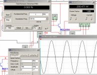
Supply voltage will be around 80 volts...and power can reach 400 watts without too much trouble to that,but really it will be rated 200 W at 8 ohms
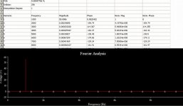
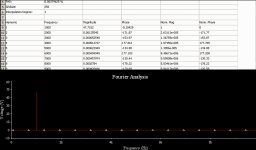
Distortion is around 0.003% (THD) at full power, fourier analisis is clean and will be able to face 2 ohms loads having 2.2uf in paralell.
I am working, and soon you gonna see prototype and final schematic posted.
Competition!..watch your back cushion shock absorbers because Dx will star to kick some....
Merry Christmas folks!
regards,
Carlos
Based into the Dx HRII, the DXM (Dx-M) will have the so loved CCS into the differential amplifier (market pressure), also current sink.
Second stage, the VAS, use dual transistors
The amplifier continue bootstrapped, of course!
Will study some different style of protection (Sakis wants that for professional applications) and will be tuned for SONICS during this last month of 2009...will be my Christmas gift to all forum friends.
Dx-M is easy to pronounciate, despite in my mind it will be Dx sonics, will not be released if not able to beat 90 percent of forum amplifiers and commercial amplifiers (related sonics)
Supply voltage will be around 80 volts...and power can reach 400 watts without too much trouble to that,but really it will be rated 200 W at 8 ohms
Distortion is around 0.003% (THD) at full power, fourier analisis is clean and will be able to face 2 ohms loads having 2.2uf in paralell.
I am working, and soon you gonna see prototype and final schematic posted.
Competition!..watch your back cushion shock absorbers because Dx will star to kick some....
Merry Christmas folks!
regards,
Carlos
Attachments
Last edited:
The amplifier will be based into the Dx HRII, that was based into the
Dx amplifier and referenced into Aksa products.
The HRII schematic is here:
Greg's Web Site
DIY group of skilled designers!...watch your back... keep back bumpers against the wall...more protected as accidental crashes happens!
hehehehhe
Carlos
Dx amplifier and referenced into Aksa products.
The HRII schematic is here:
Greg's Web Site
DIY group of skilled designers!...watch your back... keep back bumpers against the wall...more protected as accidental crashes happens!
hehehehhe
Carlos
Attachments
Last edited:
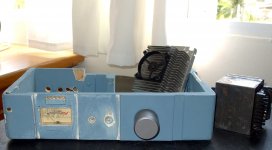
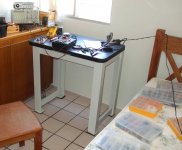
I am preparing the DXM enclosure
Soon will start to assemble prototype and to research protection...well, will try a protection if the one does not kill sonics.
I am having a lot of fun.... i love to build amplifiers!
regards,
Carlos
Soon will start to assemble prototype and to research protection...well, will try a protection if the one does not kill sonics.
I am having a lot of fun.... i love to build amplifiers!
regards,
Carlos
Attachments
Last edited:
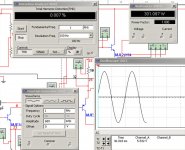
Well, already simulated the basic schematic and will go to assemble tomorrow
Today will prepare the board, will be prototype style, a lot of square blocks or copper.
For now, the good life, listening the Dx TriAmp while i am thinking what to do first.
regards,
Carlos
Today will prepare the board, will be prototype style, a lot of square blocks or copper.
For now, the good life, listening the Dx TriAmp while i am thinking what to do first.
regards,
Carlos
Attachments
Member
Joined 2009
Paid Member
Second stage, the VAS, use dual transistors
This feature gets my vote.
I have used into the HRII and also Precision 1 a long time ago
Now will continue to use into the top performance amplifiers (Dx line)
watch the HRII schematic and you gonna see the 2 stage VAS.
DXM will be based into this one, with some modifications.
Already simulated, now will go to assemble and to listen..and this is what matters...into simulators they use to be wonderfull, when playing not always.
Carlos
Attachments
Last edited:
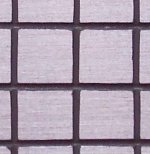
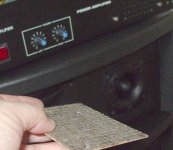
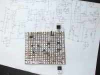
The method i use to fast produce squared islands boards
Alike na universal circuit board, the one with holes and a lot of squared pieces of copper.
The fast way to produce prototypes...also has the advantage that you solder into the copper side, this way no shorts bellow the board...and we know the mess while we are assembling, this happens.... having board insulated, will not happens shorts and you will see the circuit the way it is, nothing inverted and nothing needing you to rotate the board to inspect copper lines to follow the circuit..this way everything is in front of you eyes...connection lines, parts and solder.
Here is a small video..sorry the bad quality, my camera is not fine....but you may understand and may use the method.
I use to do this way since 1969.... so, if this is SMD, then i am the one have invented SMD
YouTube - How to create square islands into copper board.avi
ahahahahahah!
regards,
Carlos
Attachments
Last edited:

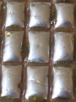
Here is the board solder points close up
Not a good idea to remove the solder flux for a while.... if you remove will be easy to produce shorts between the solder points, the flux keeps some surface tension that avoids shorts.
Clean flux after finish all construction and test.... cleaning is final thing to be done, the flux removal.
regards,
Carlos
Attachments
Hello Taj, i am glad to see you here.
About output pairs quantity i am still thinking about...because this depends if i wil use the E/I protection or not (working not good in the simulator)
With the protection installed, you kill sonics and save power transistors, a matter of decision to be taken.
Yep, the old and good 2SC5200 and 2SA1943 can be used, also others alike MJL21193/MJL21194, and J415/J425.
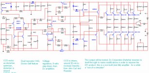
I am collecting some ideas from forum folks... From John Curl and Roender, the increase into driver's current to increase linearity... from MJL21193 i am capturing (stealing) the CCS into the differential, also Bigun and Ostripper use this too, from the lovely company, the Electrocompaniet i am using a CCS to feed the drivers, from my own circuits the rail voltage regulator, maybe will use rail diodes (positive and negative) as Mr. Hugh Dean use, the old bootstrapp circuit feeding VAS and biasing output will be used too, current sink, double transistor VAS (Doctor Self)...well.... a collection of interesting ideas that i intend to put to play together...will see if it will sound fine, i hope it will.
I will be removing features if needed, will listen and compare with the CCS and without the CCS, in the past i have perceived lower distortion and more punch at the bass.
Will start to assemble the prototype to inspect waveforms and to listen.... in 24 hours i will have something playing into real world...not pretty,but reproducing a pretty nice sound (I hope)
regards,
Carlos
About output pairs quantity i am still thinking about...because this depends if i wil use the E/I protection or not (working not good in the simulator)
With the protection installed, you kill sonics and save power transistors, a matter of decision to be taken.
Yep, the old and good 2SC5200 and 2SA1943 can be used, also others alike MJL21193/MJL21194, and J415/J425.
I am collecting some ideas from forum folks... From John Curl and Roender, the increase into driver's current to increase linearity... from MJL21193 i am capturing (stealing) the CCS into the differential, also Bigun and Ostripper use this too, from the lovely company, the Electrocompaniet i am using a CCS to feed the drivers, from my own circuits the rail voltage regulator, maybe will use rail diodes (positive and negative) as Mr. Hugh Dean use, the old bootstrapp circuit feeding VAS and biasing output will be used too, current sink, double transistor VAS (Doctor Self)...well.... a collection of interesting ideas that i intend to put to play together...will see if it will sound fine, i hope it will.
I will be removing features if needed, will listen and compare with the CCS and without the CCS, in the past i have perceived lower distortion and more punch at the bass.
Will start to assemble the prototype to inspect waveforms and to listen.... in 24 hours i will have something playing into real world...not pretty,but reproducing a pretty nice sound (I hope)
regards,
Carlos
Last edited:
Here you have the previous (untested real life) schematic
For sure will work, but will need some tuning and neutralization.
You see, remembers the HRII and the Precision 1.... well, of course is based on them.
This is the best i can do..will listen today.
regards,
Carlos
For sure will work, but will need some tuning and neutralization.
You see, remembers the HRII and the Precision 1.... well, of course is based on them.
This is the best i can do..will listen today.
regards,
Carlos
Attachments
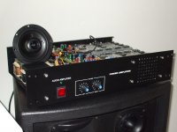
Build a Dx amplifier, a guarantee of satisfaction
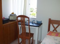
Here you have the Dx TriAmp that is sounding absolutelly lovely!
And the other picture is the Dx Corporation Support Staff... this personnel has expertise in the logistic to feed the supplies stock.
When you build a Dx Amplifier you're building tradition and sonic excelente..the only one defended by the 300 from Sparta... there are more than 300 satisfied builders of this DIY brand.
Carlos
Attachments

Last edited:
Member
Joined 2009
Paid Member
Carlos,
When I was playing with the simulator and looking at double transistor VAS for TGM3 I noticed that there were some benefits if you split Cdom so that each VAS device has it's own Cdom capacitor - kind of like two-pole compensation that Dr. Self also loves very much. I never built this circuit so I don't know if it works well or sounds good but perhaps you can consider this ?
p.s. I love the 'DX PCB' technique !
I will try during the listening tests...because at the simulator
i cannot see the advantage (my know how to use simulators and some analisis is very limited).
Will split and listen.
I would like to find Andrew T, he made a suggestion, one day in the past, to include a low ohm resistance into the VBE multiplier, i want to try his idea too.
thank you,
regards,
Carlos
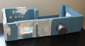
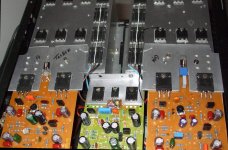
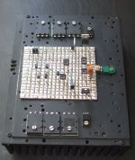
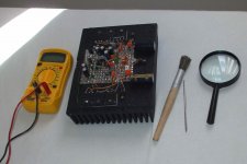
DXM protype is ready to play tomorrow morning
a few connections, adjustments and them pleasant moments!
Metalic plates are shield, it is grounded, a ground plane if you want to understand this way.... a flying over ground plane.
regards,
Carlos
a few connections, adjustments and them pleasant moments!
Metalic plates are shield, it is grounded, a ground plane if you want to understand this way.... a flying over ground plane.
regards,
Carlos
Attachments
Last edited:
This new forum attachment feature is bothering me a lot!
Delay too much and it is failing.
Because of that i will upload to a hostess site.
Metal blades are shields folks.
regards,
Carlos
Delay too much and it is failing.
Because of that i will upload to a hostess site.
Metal blades are shields folks.
regards,
Carlos
An externally hosted image should be here but it was not working when we last tested it.
Last edited:
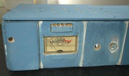
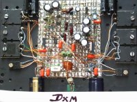
DO NOT BUILD! .... result a lemmon!
I found unstabilities, then the CCS was removed and the traditional circuit was assembled in place... sound stérile...then i have removed the CCS to drivers, result much better...well.... finally, resulted alike Precision 1
No reason to build another Precision 1.... it is good enougth.
The project is dead...not aproved by the Dx Corporation Chairman.
Thank you and sorry by the bad results...yeah!..maybe my board.
Audio quality had not advantage compared to earlier Dx products!..not acceptable this way.
regards,
Carlos
Attachments
Member
Joined 2009
Paid Member
Not so fast...
We received some expectations from DX corporation on something new and exciting. We are asking the Chairman not to suspend operations at the first hurdle, please ?
I like the photo giving side view, looks like components are trying to walk with their feet caught in some sticky silver mud !
If we have to stop here I would at least be interested to learn more of why it got stuck, for my learning at least - I didn't fully understand the instability - is it with the CCS loading of the LTP, or the CCS loading of the driver stage ? where do think is the problem - where is the too many phase shifts occuring ?
- Status
- This old topic is closed. If you want to reopen this topic, contact a moderator using the "Report Post" button.
- Home
- Amplifiers
- Solid State
- I am proud to announce the Dx-M, 300 wiskies of power with a very low distortion