I don't think there is any real standard for this specification. It could be primary impedance or percent of total primary turns. But very doubtful it's inductance. The only way to know for sure is to contact the manufacturer and ask. If you had one in hand, you could make a simple low voltage AC test measurement to find out which. But my gut feel leans toward total primary turns because that's how UL screen taps are usually specified.
Last edited:
hey-Hey!!!,
Dynaco advertised its CFB output by turns ratio. They claimed 15%, and it was just a bit over 17 if memory is still intact...") The Chicago BO-6 is also advertised by turns ratio, and their BO-14 has no lableing as to its turns ratio( it is 10% by turns to the anode coil ). The a-a loading is also taken independantly of the CFB coil; the effective load is higher( 1.15^2*listed a-a load for the BO-6 for instance ).
The Chicago BO-6 is also advertised by turns ratio, and their BO-14 has no lableing as to its turns ratio( it is 10% by turns to the anode coil ). The a-a loading is also taken independantly of the CFB coil; the effective load is higher( 1.15^2*listed a-a load for the BO-6 for instance ).
cheers,
Douglas
Dynaco advertised its CFB output by turns ratio. They claimed 15%, and it was just a bit over 17 if memory is still intact...
The Chicago BO-6 is also advertised by turns ratio, and their BO-14 has no lableing as to its turns ratio( it is 10% by turns to the anode coil ). The a-a loading is also taken independantly of the CFB coil; the effective load is higher( 1.15^2*listed a-a load for the BO-6 for instance ).cheers,
Douglas
whoops............... i think that's of the second winding
it was used before the nfb was taken from the speaker out-put socket
diyers in the 50s would put their own on the out side of transformer with a bit of card and tape
now days i think its best to come off the speaker socket with a resistor and cap
even though this can change the impedance set-up.
it was used before the nfb was taken from the speaker out-put socket
diyers in the 50s would put their own on the out side of transformer with a bit of card and tape
now days i think its best to come off the speaker socket with a resistor and cap
even though this can change the impedance set-up.
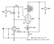
CFB is usually specified as percent of primary turns. In other words, a percentage of primary voltage that gets fed back to the cathode. (10% CFB for a primary with 2000 turns of wire would have a completely separate winding of 200 turns of wire.) I love using CFB with Class A pentodes with separate G2 supplies and Class A2 triodes. To me CFB beats UL connect in pentodes every time. You can also get some very good dampening factors with high Mu transmitting triodes too. Electra-Print and Edcor are very willing to custom wind what ever you need.
Rgs, JLH
Rgs, JLH
To me CFB beats UL connect in pentodes every time.
Rgs, JLH
CFB is U-L as far as the g2 is concerned( with fixed g2 voltage ).
cheers,
Douglas
Hey Douglas,
Think you will find this one interesting, written by D.T.N. Williamson and Peter J. Walker:
http://www.dc-daylight.ltd.uk/Valve-Audio-Interest/Articles-for-the-Web/Amplifiers-and-Superlatives/Amplifiers-and-Superlatives.pdf
It might make you change your mind. If not, it´s anyway interesting reading from two gurus of that time.
Think you will find this one interesting, written by D.T.N. Williamson and Peter J. Walker:
http://www.dc-daylight.ltd.uk/Valve-Audio-Interest/Articles-for-the-Web/Amplifiers-and-Superlatives/Amplifiers-and-Superlatives.pdf
It might make you change your mind
. If not, it´s anyway interesting reading from two gurus of that time.Hey Douglas,
Think you will find this one interesting, written by D.T.N. Williamson and Peter J. Walker:
http://www.dc-daylight.ltd.uk/Valve-Audio-Interest/Articles-for-the-Web/Amplifiers-and-Superlatives/Amplifiers-and-Superlatives.pdf
It might make you change your mind
I read that one long ago, and it is not much more than personality ahead of principle IMO. The g2-cathode voltage change as a fraction of plate voltage change defines U-L. it does not matter at all if we move the cathode to the screen, or the screen towards the cathode( assuming a drop in anode V in this example). That it isn't just moving g2-cathode is another topic altogether.
cheers,
Douglas
Have you verified your theoretical findings IRL or by simulation?
Would you be so kind as to explain *WHY* it would matter?
cheers,
Douglas
"BECAUSE" I´m interested in the subject.
Why would you expect any analysis/simulation/measurement to provide a different answer?
cheers,
Douglas
I have always wondered if a floating screen supply for a cathode feedback output stage would be practical. (I mean, besides it being a bunch of effort and parts) I have no idea how much stray capacitance that would introduce to the cathode circuit or if the cathode would even notice. Does anyone do this?
I have always wondered if a floating screen supply for a cathode feedback output stage would be practical. (I mean, besides it being a bunch of effort and parts) I have no idea how much stray capacitance that would introduce to the cathode circuit or if the cathode would even notice. Does anyone do this?
hey-Hey!!!,
There is no way to do this for PP with a single screen supply. SE would be possible, but the U-L behaviour from a fixed supply is IME a benefit. McIntosh solved the PP implementation quite elegantly, but it requires g2 voltage equal to the plate.
cheers,
Douglas
You guys can argue all you want about UL vs. CFB. However, I will tell you that in my experiments the CFB setup sounded more focused and resolved the nuances better than UL connection. Image stability was also better.
The OPT was wound with a 40% UL tap, so I was able to compare UL with CFB. It is important to understand that this was not without some changes to the operating point. As all you know, any time the operation point changes, the sound can change too. I just want to be most forth coming on the differences.
To compare I setup the amplifier in CFB configuration and listened for about 2 weeks. To swap to UL I did the following: Unhooked the CFB winding and inserted a 20 ohm resistor to keep the bias the same. I had to do this due to the DCR of the CFB winding being removed. I unhooked the G2 connection from +B2 supply and hooked it up to the 40% tap on the OPT. Lastly, I inserted a string of OB3 gas discharge tubes and resistors to take up the current left over from G2 not being hooked up to the +B2 supply. This kept the voltages the same across the CCS and driver tube.
Even though I tried to makes this a very close A/B of UL vs. CFB there were operation point differences. The most obvious being the G2 voltages. In CFB configuration the G2 voltage was 300V. In the UL configuration the G2 voltage became 345V due to being tired to the 40% tap on the OPT.
After converting to UL connection I listened for 4 days. On the fifth day I went back to CFB because it was obvious from the first minute is was superior sounding. YMMV, but that is the outcome from my little experiment with CFB vs. UL.
Rgs, JLH
Attachments
- Status
- This old topic is closed. If you want to reopen this topic, contact a moderator using the "Report Post" button.
- Home
- Amplifiers
- Tubes / Valves
- Question - Output Trafo with CFB