Now that I have your attention  I dont mean it is good for every circumstance. For instance in a Class A common source output stage like a Zen amp (what is the sound of one mosfet clapping?) it would be bad because as the drain current increases, the transconductance increases and so the drain gets pulled down further by the signal than if the transconductance stayed constant with current - which in a mosfet it increases in a hyperbolic way with increase in current. So the waveform gets distorted with a second harmonic - a sinewave becomes pointy at the bottom and blunt and rounded somewhat on the top. Not good.
OK then, what's all this good non-linearity stuff? This. (and this is only my observations and thoughts, if you think it's wrong then tell me why) If you run your mosfet as a *source follower* and it is driving a resistive load (for the sake of simplicity) then as the load gets pulled upward the fet source has to supply more current to the load so the mosfet has to turn on harder and the only way it can do that is to let the rising source not rise quite as far as the rising gate so that the gate-source voltage will increase. Of course this means that the source falls further and further behind as the output gets driven higher and higher. Conversely, as the output swings downward the current drain from the source decreases and so the source is better able to track the changing gate voltage. This of course means that the output waveform has some sort of offsett because it tracks the positive and negative half cycles differently.
Now this *would* be the case if the transconductance was constant with changes in current. However, what we actually find (or rather, what I think it is that I observed in my experiment (heatsinks hot enough to smell; no simulators here!)) is that as the output signal rises the source (load) current increases and luckily SO DOES THE TRANSCONDUCTANCE! This means that the source would want to start to lag behind the gate as before and make distortion but the *proportionally* increasing transconductance comes to the rescue and very much reduces this lazy source follower!
But wait, there's more! As the output swings downward the opposite happens too. The reduced source current means reduced transconductance and so the output doesn't swing as far down as it would otherwise.
My experimental setup (using a totally unsuitable 500v 32 amp 460 watt switching mosfet) was a 40v dc supply, 5 ohms in the source lead and an adjustable bias supply. With 3.5 amps through the fet and 16 volts p/p sinewave going into the gate, the source (with the scope AC coupled) swung to +7.8 volts and -7.85 volts, a shortfall of 200mV and 150mV respectively. Almost equal, which is the big deal. Load current is +/- 1.6 amps. Almost no 2nd harmonic and so presumably not much of others either.
I hope somebody gets the point of all this. In short, it would seem that if you use a mosfet who's transconductance vs. drain current corresponds to the load resistance then the varying transconductance will help reduce distortion, but *ONLY* in a source follower cct, not in a common source.
Well, that's it.
I dont mean it is good for every circumstance. For instance in a Class A common source output stage like a Zen amp (what is the sound of one mosfet clapping?) it would be bad because as the drain current increases, the transconductance increases and so the drain gets pulled down further by the signal than if the transconductance stayed constant with current - which in a mosfet it increases in a hyperbolic way with increase in current. So the waveform gets distorted with a second harmonic - a sinewave becomes pointy at the bottom and blunt and rounded somewhat on the top. Not good. OK then, what's all this good non-linearity stuff? This. (and this is only my observations and thoughts, if you think it's wrong then tell me why) If you run your mosfet as a *source follower* and it is driving a resistive load (for the sake of simplicity) then as the load gets pulled upward the fet source has to supply more current to the load so the mosfet has to turn on harder and the only way it can do that is to let the rising source not rise quite as far as the rising gate so that the gate-source voltage will increase. Of course this means that the source falls further and further behind as the output gets driven higher and higher. Conversely, as the output swings downward the current drain from the source decreases and so the source is better able to track the changing gate voltage. This of course means that the output waveform has some sort of offsett because it tracks the positive and negative half cycles differently.
Now this *would* be the case if the transconductance was constant with changes in current. However, what we actually find (or rather, what I think it is that I observed in my experiment (heatsinks hot enough to smell; no simulators here!)) is that as the output signal rises the source (load) current increases and luckily SO DOES THE TRANSCONDUCTANCE!
This means that the source would want to start to lag behind the gate as before and make distortion but the *proportionally* increasing transconductance comes to the rescue and very much reduces this lazy source follower! But wait, there's more! As the output swings downward the opposite happens too. The reduced source current means reduced transconductance and so the output doesn't swing as far down as it would otherwise.
My experimental setup (using a totally unsuitable 500v 32 amp 460 watt switching mosfet) was a 40v dc supply, 5 ohms in the source lead and an adjustable bias supply. With 3.5 amps through the fet and 16 volts p/p sinewave going into the gate, the source (with the scope AC coupled) swung to +7.8 volts and -7.85 volts, a shortfall of 200mV and 150mV respectively. Almost equal, which is the big deal. Load current is +/- 1.6 amps. Almost no 2nd harmonic and so presumably not much of others either.
I hope somebody gets the point of all this. In short, it would seem that if you use a mosfet who's transconductance vs. drain current corresponds to the load resistance then the varying transconductance will help reduce distortion, but *ONLY* in a source follower cct, not in a common source.
Well, that's it.
Hi,
we made lot of source follower type amplifier. We didn't measure the distortion, but we found, that we have to use high bias for good quality sound. The best sounding cheap FET is the IRF520, or for higher dissipation IRF840. Unfortunately IRFP series (such as IRFP150, 250, 360,450) has nonlinear transfer characteristics under 10A, and they are useful only as current generator.
The only problem with this amlifier is the low output power due the poor thermal parameters of TO-220 package. Dissipation over 40W, is real pain.
We used valves to drive this amplifiers, and we use no feedback. The most simplest amplifier with one half of E88CC, and two IRF840 (one as source follower, and one as current regulator), gives some 7.5-8W oput power, with gain of 20-25dB, and very high input impedance.
Sajti
mosfets
hey circlotron-this is interesting stuff.
it is slightly over my head cos i dont know yet what a source follower is ..transconductance..,,
i want to know what all this stuff is..the terms,and what the circuits look like and how they function-
im doing diploma i nelectrotech-next semester we do op amps and such like..+ i have some ETI articles on basic amp stuffs,so il read them..right after my test this week
when i read up on what those things are....il tell u what i think lol
20-20 hindsight
The day after I posted this I began to conclude I was thinking a load of rubbish. For example, a source follower driving a resistive load, once it is above the threshold voltage, if the gate voltage ramps up linearly and if the transconductance is:
(1) infinite, then the source will follow the gate exactly but a constant several volts below it. Ideal but nonexistent.
(2) finite but constant, then the source voltage will be still be an upward sloping straight line but not as steep as the gate voltage. Best real-world possibility. Transconductance of most mosfets actually becomes constant above a certain current but it might be inconveniently high.
(3) finite and increasing with current as per a normal mosfet up to a certain current, the source voltage will start off rising at a lesser rate than the gate but as the load current increases the rate of increasing source voltage gets increasingly steeper. i.e output is nonlinear.
/Circlotron - repents in sackcloth and ashes.
The day after I posted this I began to conclude I was thinking a load of rubbish.
For example, a source follower driving a resistive load, once it is above the threshold voltage, if the gate voltage ramps up linearly and if the transconductance is: (1) infinite, then the source will follow the gate exactly but a constant several volts below it. Ideal but nonexistent.
(2) finite but constant, then the source voltage will be still be an upward sloping straight line but not as steep as the gate voltage. Best real-world possibility. Transconductance of most mosfets actually becomes constant above a certain current but it might be inconveniently high.
(3) finite and increasing with current as per a normal mosfet up to a certain current, the source voltage will start off rising at a lesser rate than the gate but as the load current increases the rate of increasing source voltage gets increasingly steeper. i.e output is nonlinear.
/Circlotron - repents in sackcloth and ashes.
Thinking rather better today...
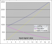
NOW I think I know what is going on! If you have a mosfet common source stage and you run the gate voltage up linearly, the drain current will increase according to the square of the gate voltage, i.e gradual at first then more energetically as the gate voltage gets higher. Now imagine you set the gate voltage to a figure of 30 units and the drain current is at 900 units. You can run the gate up or down from this 30 figure. On the graph the drain current is dark blue for 30 up and magenta for 30 down. Drain current changes way more for gate voltage going upward than it does for gate voltage going downward an equal amount as can be readilt seen on the graph.
Of course the result of this uneven up-ness and down-ness means the output signal will pull one way much more than the other, giving sinewaves a pointy top and a blunt bottom or vice versa, i.e 2nd harmonic distortion. We don't want to use that naughty mr negative feedback so we have to put our best thinking caps on.
It turns out that if we have one p-channel fet drain pulling up and another n-channel fet drain pulling down and both gates biased to the 30 units of voltage, the *combined* effect of both nonlinear drain current changes add up to a =linear= change in total drain current with linear change in drain voltage. Now we're getting somewhere!
Note the straight yellow line on the graph. This is the sum of the two drain currents at any given moment with one gate voltage running down and the other one running up as per the magenta and dark blue lines respectively.
What I am going to try next is one of my choke-loaded source follower Class A amps that I have earbashed everyone so much about for the last 6 months, and have two side-by-side source followers - one feeding each end of the load and driven in anti-phase. That way, to the extent the two source followers have a perfect square law characteristic, to that extent they will eliminate each other's distortion, with no negative feedback. Should be interesting.
NOW I think I know what is going on! If you have a mosfet common source stage and you run the gate voltage up linearly, the drain current will increase according to the square of the gate voltage, i.e gradual at first then more energetically as the gate voltage gets higher. Now imagine you set the gate voltage to a figure of 30 units and the drain current is at 900 units. You can run the gate up or down from this 30 figure. On the graph the drain current is dark blue for 30 up and magenta for 30 down. Drain current changes way more for gate voltage going upward than it does for gate voltage going downward an equal amount as can be readilt seen on the graph.
Of course the result of this uneven up-ness and down-ness means the output signal will pull one way much more than the other, giving sinewaves a pointy top and a blunt bottom or vice versa, i.e 2nd harmonic distortion. We don't want to use that naughty mr negative feedback
so we have to put our best thinking caps on. It turns out
that if we have one p-channel fet drain pulling up and another n-channel fet drain pulling down and both gates biased to the 30 units of voltage, the *combined* effect of both nonlinear drain current changes add up to a =linear= change in total drain current with linear change in drain voltage. Now we're getting somewhere! Note the straight yellow line on the graph. This is the sum of the two drain currents at any given moment with one gate voltage running down and the other one running up as per the magenta and dark blue lines respectively.
What I am going to try next is one of my choke-loaded source follower Class A amps that I have earbashed everyone so much about for the last 6 months, and have two side-by-side source followers - one feeding each end of the load and driven in anti-phase. That way, to the extent the two source followers have a perfect square law characteristic, to that extent they will eliminate each other's distortion, with no negative feedback. Should be interesting.
Attachments
Another Crazy Idea ? .....
There was an article in EW/WW yonks ago about square-law cancellation being good if implemented correctly.
Maybe somebody has a reference ?.
BTW - I reckon some of your stories (posts) should be included as a series of long winded articles (copies of your posts plus added comments detailing your researches and findings).
I find them both educational and entertaining, and I wish some of my learning texts were presented in the same humble and humorous manner that you employ here.
Maybe there needs to be a Wicki thread called "Circlotron's Fun Way With Electronics".
Keep drinking that crazy water, and keep up the good work.
Eric.
- Status
- This old topic is closed. If you want to reopen this topic, contact a moderator using the "Report Post" button.