Having started looking at a speaker project on these very forums about 3 years ago I was drawn towards a scan speak based design such as the Vogue 2 at Wilmoslow Audio. Whilst browsing on Ebay I came across a pair of Scan Speak D2905/9700 tweeters going for a good price and decided they would be a good start and could fit in with the sliced paper SP95 project on Troel Gravesen's website. Having bought them and doing a bit of research it would appear they aren't an easy swap for the 9500, so it kind of knocked that idea on the head.
As luck would have it, whilst doing some more surfing on Ebay I spotted a pair of Scan Speak 18W/8545 and there was a design incorporating both this and the 9700 on Troel's website in the form of the Amish 45/95. So this is where my journey really began..... very slowly!
It has taken a considerable amount of time for this project to get started due to house moves, holidays and various other hobbies getting in the way. Not to mention a lack of tools and space in which to undertake any construction. However, it has recently regained momentum thanks to me aquiring a few tools (router and table saw) and deciding that actually I can use my conservatory as a workshop!
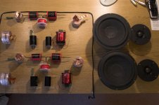
So with drive units purchased, it was time to aquire some cross-over components. This proved difficult to get exactly what I wanted in the UK and during my time searching the Amish project was updated by Troel's to provide a parallel crossover design specifically for the 9700... which was a bonus. I decided to bite the bullet and order my parts from Madisound and have them shipped over, knowing I would get stung for import duty, but it still worked out considerably cheaper than my other searches.
The picture below show the components all laid out in their glory, well bar a couple of resistors that had to be sourced from elsewhere.
As luck would have it, whilst doing some more surfing on Ebay I spotted a pair of Scan Speak 18W/8545 and there was a design incorporating both this and the 9700 on Troel's website in the form of the Amish 45/95. So this is where my journey really began..... very slowly!
It has taken a considerable amount of time for this project to get started due to house moves, holidays and various other hobbies getting in the way. Not to mention a lack of tools and space in which to undertake any construction. However, it has recently regained momentum thanks to me aquiring a few tools (router and table saw) and deciding that actually I can use my conservatory as a workshop!
So with drive units purchased, it was time to aquire some cross-over components. This proved difficult to get exactly what I wanted in the UK and during my time searching the Amish project was updated by Troel's to provide a parallel crossover design specifically for the 9700... which was a bonus. I decided to bite the bullet and order my parts from Madisound and have them shipped over, knowing I would get stung for import duty, but it still worked out considerably cheaper than my other searches.
The picture below show the components all laid out in their glory, well bar a couple of resistors that had to be sourced from elsewhere.
Attachments
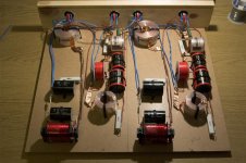
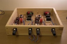
As I was waiting to collect sheet material and the table saw I figured I would kick off with the crossover now that I had all the parts. I decided due to the size of the coils and caps that I would build a separate cabinet for the crossover network. This would then fit neatly into the rack with the rest of my hi-fi and hopefully make a good talking point. Having spent some time working with pro-audio gear I have become very fond of the Speakon connectors as they support large cables, have four (or eight) pins and are very secure. This made them an ideal choice for the links in and out of the crossover as I mean I could keep the cable count down to single runs of 4-core cable, thus supporting bi-wire / bi-amping on the input side and obviously the split of low and high frequency signals to the speakers themselves. I’ve opted to fit these to the cabinets as well and to ensure that it is all neat and tidy I have a pair of right angle versions of the plugs.
The pictures show the crossover when I was initially constructing it and nearing completion, it needs the lid fitting and the box given some form of exterior treatment.
The pictures show the crossover when I was initially constructing it and nearing completion, it needs the lid fitting and the box given some form of exterior treatment.
Attachments
I guess what I have failed to state is a bit of the background and my drivers for this project. I have been interested in audio reproduction from a very young age and I was always looking for things to fiddle with and try and understand how they worked. For my GCSE Design Technology project I built my first pair of speakers using some drive units from Tandy (Radio Shack) and crossover components from Russ Andrews. It was a very simple 1st order crossover using the book I bought from Tandy… terms like Baffle Step Compensation just didn’t even figure for me back then. Still I ended up for a pair of speakers that were better than the old Fidelity ones I had been using and kept me going until my university years.
At this point I bit the bullet and bought some TDL RTL3 SE, which were great, loads of bass and great for parties. The TDLs followed me around faithfully for a number of years, seeing some changes to the kit in my rack, a Marantz CD67SE (later upgraded with a Cambridge Audio DAC), a Marantz PM30SE Amp replaced by an Audiolab 8000S before finally being replaced by a pair of Monitor Audio Silver 9is (which I am still using). Again things moved on again in the rack, the cd player became a two box combo of an Audiolab 8000CDM and Tag McLaren DAC20 and an Audiolab 8000SX was added to the amp section to allow bi-amping.
Along side this I got involved in sound engineering for a soul band, that eventually became a rock back… then another. This gave me the opportunity to play with some bigger toys and also give me more of an appreciation for the sound of live instruments. There were all sorts of combos in this, the very first setup being some strange wooden box amps that knocked out about 200W each and some very badly modified Peavey PA speakers. I had great fun restoring these to factory setup and then embellishing them with some foam insulation. From there it was a blur of powered mixers, mix and match speakers and some new fangled toys in the form of compressors and limiters. On of my favourite set ups was a full Peavey rig with two 15” bass bins with one 15” and horn top per channel powered by a 1000W/ch amp for the bass and 550W/ch for the tops, with a Behringer electronic crossover for good measure. It sounded great, but the amp rack weighed about 60kg! We finally settled on a fully active setup, combining Mackie tops and monitors with Electovoice bass bins, a combined front of house total of about 2500W…
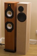
And back to the thread… I was very pleased with my home set up and this was where I had wanted to be for a long time… but (and there had to be a but otherwise we wouldn’t be here) after building some furniture to house said hi-fi there was something niggling me, mainly the fact that all the furniture and the flooring was oak and my speakers were cheery! So I started looking around at what I could replace the MAs with and I was struggling to find something in the right price range that I really liked and that was when one of my friends said, “why don’t you just build some?”
Red rag to a bull!
At this point I bit the bullet and bought some TDL RTL3 SE, which were great, loads of bass and great for parties. The TDLs followed me around faithfully for a number of years, seeing some changes to the kit in my rack, a Marantz CD67SE (later upgraded with a Cambridge Audio DAC), a Marantz PM30SE Amp replaced by an Audiolab 8000S before finally being replaced by a pair of Monitor Audio Silver 9is (which I am still using). Again things moved on again in the rack, the cd player became a two box combo of an Audiolab 8000CDM and Tag McLaren DAC20 and an Audiolab 8000SX was added to the amp section to allow bi-amping.
Along side this I got involved in sound engineering for a soul band, that eventually became a rock back… then another. This gave me the opportunity to play with some bigger toys and also give me more of an appreciation for the sound of live instruments. There were all sorts of combos in this, the very first setup being some strange wooden box amps that knocked out about 200W each and some very badly modified Peavey PA speakers. I had great fun restoring these to factory setup and then embellishing them with some foam insulation. From there it was a blur of powered mixers, mix and match speakers and some new fangled toys in the form of compressors and limiters. On of my favourite set ups was a full Peavey rig with two 15” bass bins with one 15” and horn top per channel powered by a 1000W/ch amp for the bass and 550W/ch for the tops, with a Behringer electronic crossover for good measure. It sounded great, but the amp rack weighed about 60kg! We finally settled on a fully active setup, combining Mackie tops and monitors with Electovoice bass bins, a combined front of house total of about 2500W…
And back to the thread… I was very pleased with my home set up and this was where I had wanted to be for a long time… but (and there had to be a but otherwise we wouldn’t be here) after building some furniture to house said hi-fi there was something niggling me, mainly the fact that all the furniture and the flooring was oak and my speakers were cheery! So I started looking around at what I could replace the MAs with and I was struggling to find something in the right price range that I really liked and that was when one of my friends said, “why don’t you just build some?”
Red rag to a bull!
Looking forward to hearing more. I bought some 2nd hand 'Vogues' a few years back but it turns out that they weren't actually Vogues at all. The crossover was not the original Wilmslow design and the cabinet actually had a divider to reduce the internal volume by half. I've never been too happy with them but I just haven't got around to sorting them out. I've actually got the components for the Vogue crossover, I just need to connect it all up and give them a go. Maybe this thread will inspire me
I strongly considered building the Amish at one point but already having cabinets for the Vogue (with the full internal volume reinstated) it seemed an expensive option.
Anyway, good luck with the Amish build.
Mike
I strongly considered building the Amish at one point but already having cabinets for the Vogue (with the full internal volume reinstated) it seemed an expensive option.
Anyway, good luck with the Amish build.
Mike
Just in case anyone isn’t familiar with Troel’s website, the link to this project is:
Scan-
Hi Mike, I was reading about your fun and games with your “Vogue 2”. I hope you do find the inspiration to plough on and get them back as intended, it’ll be worth the effort I am sure. Thanks for the words of encouragement.
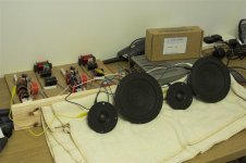
Where were we? Oh yes, so my crossovers are practically done and I have been trying them with the drivers arranged on the desk just to make sure that everything was ok. Just from these trials I am excited about how these are going to work out, vocals are already amazing and things like cymbals sound great. This is being fed from a Denon mini-system with either CDs or MP3s, so when they finally get their chance on the main system I am hoping they’ll really sing.
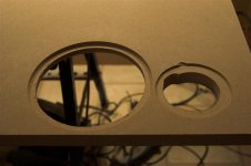
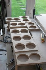
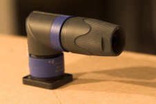
Ok, so now we are in the process of cabinet building and my first step was to find some tutorials on here and on YouTube as to how to build and use a circular cutting jig. Thankfully this is actually fairly straightforward and I got one knocked up for my router pretty quickly. The trick is marking out and drilling all the points that you are likely to need before you start, as it saves time later. I am using a 12mm bit in my router and you can see the marks on the attached photos for the various hole sizes to allow rebating for the flanges and through cutting for the back of the drivers.
Scan-
Hi Mike, I was reading about your fun and games with your “Vogue 2”. I hope you do find the inspiration to plough on and get them back as intended, it’ll be worth the effort I am sure. Thanks for the words of encouragement.
Where were we? Oh yes, so my crossovers are practically done and I have been trying them with the drivers arranged on the desk just to make sure that everything was ok. Just from these trials I am excited about how these are going to work out, vocals are already amazing and things like cymbals sound great. This is being fed from a Denon mini-system with either CDs or MP3s, so when they finally get their chance on the main system I am hoping they’ll really sing.
Ok, so now we are in the process of cabinet building and my first step was to find some tutorials on here and on YouTube as to how to build and use a circular cutting jig. Thankfully this is actually fairly straightforward and I got one knocked up for my router pretty quickly. The trick is marking out and drilling all the points that you are likely to need before you start, as it saves time later. I am using a 12mm bit in my router and you can see the marks on the attached photos for the various hole sizes to allow rebating for the flanges and through cutting for the back of the drivers.
Attachments
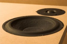
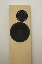
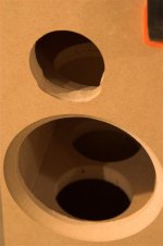
So with the jig built it was time to get some practice in and see how they work out. Things seemed to go pretty well with the first tweeter cut out, getting a good depth for the rebate and a clean circle. Unfortunately the hole was about 1mm too small, so I had a go at free hand cutting to open it up, which worked ok (not the tidiest job) and then I managed to nick the edge whilst taking a segment out of the actual through hole. DOH!
The woofer cut-out went according to plan and the depth of cut was spot on. So not a bad start really and it gives me a good idea of what these are going to look like.
The woofer cut-out went according to plan and the depth of cut was spot on. So not a bad start really and it gives me a good idea of what these are going to look like.
Attachments
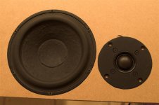
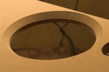
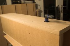
With a woofer hole cut it was time to try a chamfering tool, exciting stuff! I should thank Aldi at this point for my router bit set which cost me something like £7 and has 12 pieces in it. This process is thankfully fairly idiot proof and I love how neatly it looks when it’s finished. Shame there is only two of these as I could chamfer holes all day… and not that’s not a euphemism for something else!
Attachments
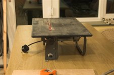
My next challenge is making some modifications to the table saw that a friend lent me to make it large enough to cut the MDF sheets I have sufficiently accurate for the cabinets to have a goof fit without lots of trimming and sanding. The top plate currently only allows for cuts 200mm wide, so to extend this out a sheet of 12mm MDF will bit fitted to the top with the blade slot routed out. A datum line can then be drawn where the blade protrudes such that it gives a reference point from which to measure. As a guide I’ll be using L shaped aluminium extrusion, which will be clamped to the “new” table top. So basically I have a project within my project!
Fingers crossed I can get this knocked up tonight and a few test cuts made, such that I can report good news… and hopefully there will be no loss of digits along the way!
Fingers crossed I can get this knocked up tonight and a few test cuts made, such that I can report good news… and hopefully there will be no loss of digits along the way!
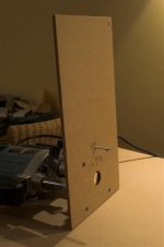
Well, the good news is that I still have all my digits today! The other good news is that I managed to achieve my aim of extending the table saw and even got as far as getting my test piece through.
Attachments
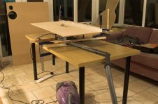
Of course there were lessons to be learnt along the way, such as manhandling a 1.2m x .8m x 25mm sheet of MDF by one’s self and running it through a relatively small table saw is not without challenges. It was when I was halfway through cutting the sheet when it occurred to me that I was going to run into an issue when I got to the end of the cut in the fact that I could easily end up dropping the pieces (more stuff than hands). It’s incredible how a quickly spinning saw blade focuses the mind and I managed to gentle get both out of the way without incident.
The second lesson was the 9mm (I was going to use 12mm, but had a last minute change of heart) extended table top does have some flex in it when faced with the large sheets I am cutting. Tonight I am going to add legs to each corner of the table to reduce the flex and improve the amount of support that the table provides to the work piece. This will have the added bonus of making the cuts a bit cleaner. I may also use my other workbench to provide a supplementary support for the larger pieces.
What I was very pleased with is that using the aluminium extrusion to draw out a datum line has meant that the cuts are spot on the distance from this line, thus no fudge factor is required.
Below is a picture of my very messy temporary workshop!
Attachments
The vacuum extraction is a bit hit and miss, it depends on the tool and which orientation you have that tool in. It works pretty well for the circular saw, table saw and the sander, not so good on the router, which makes the most mess! I had to empty the bag twice yesterday I made that much dust… thankfully I bought some dust masks as that MDF dust is not pleasant.
Last night I got all the pieces cut out, so that is the front, back, sides, top, bottom and braces. The braces have been routed out and will need to be chamfered to tidy them up. I tried a dry assembly to see how accurately the cuts had been and its pretty decent for a first attempt. The tops, bottoms and braces are all about 1mm too wide, such that when they are matched with the sides there is a slight overhang compared with the fronts and backs. I’ll either sand these down or run them through the table saw again to get a clean fit.
In terms of the actual panels, they are:
Front and back: 960x190x25mm
Sides: 960x230x18mm
Tops, bottoms and braces: 230x154x25mm (except 1 which is 18mm for between the drive units)
My plan is to screw and glue them and I don’t have large enough clamps to go for a glue only assembly. This also means that I can remove the front panel during testing to make sure everything is as it should be and the foam stays in place. The assembly process will involve having the cabinet upside down, such that everything is referenced to the top, which will hopefully result in the best finish being at the critical point from an aesthetic point of view.
One thing that I haven’t cut out or decided on is the plinths, I think I’ll sandwich a piece of 25mm and 18mm MDF to form a nice substantial base, then use a round edge router bit to give a tidy finish. I’m not sure how big to make this, but will do a bit of experimenting once the cabinets are assembled.
I must get on and order the damping sheets and infill material, along with a port… any suggestions other than Wilmslow Audio for these items in the UK?
Oh and I'll post some pictures later, as the memory stick which had them on has decided to corupt it's self!
So this evening is going to be spent preparing the rest of the pieces for the cabinets. The braces need tidying up, they have the holes cut out, but they need sanding down and the edges chamfering to give them a nice finish. Also they are about 1mm too wide, so I am going to run them back through the table saw to get them down to the right size for a tollerable fit.
The front baffles need the driver apetures cutting, which means I need to come up with a solution to cut the little notch out for the tweeter. All in all things are progressing nicely, though I am not looking forward to the clean-up operation when this is all done!
The front baffles need the driver apetures cutting, which means I need to come up with a solution to cut the little notch out for the tweeter. All in all things are progressing nicely, though I am not looking forward to the clean-up operation when this is all done!
No, I hadn't thought of them. Having spent lots of time browsing RS and Maplins, I sort of gave up on that type of establishment as they didn't seem to cater for crossover building. Just had a quick squiz and they have a good array of inductors, but couldn't find any decent sized caps. Maybe its just late and the MDF dust has gone to my head!
I have been banging my head against the wall trying to get the tweeter hole just right and I kept getting it about 1/2mm too small. So after 4 attempts to get the jig right I am finally happy with the results and can start on the actual front panels now. However, I did get some freehand practice with the router earlier and i can now make a much neater job of the notches in the tweeter hole.
The braces, tops and bottoms are all the right size and have now been cleaned up and chamfered (photos to follow), which means tomorrow I can get the pilot holes drilled and match panels up to give the best fit. Its all getting quite exciting now!
Friday night and Saturday proved to be very productive (sad I know, I should have been down the pub)
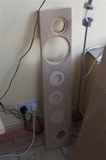
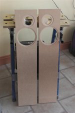
Anyway, I got cracking with making sure the jig was just right for cutting the tweeter holes and then prepared both baffles, which thankfully turned out very nicely. As you can see in the photo the test piece took a battering, but it was worth it in the end.
Also shown are the braces all ready for installation.
Attachments
I got all the holes drilled on the sides, fronts and backs... or was at least most of the way through when I realised that I had cocked it up and got the holes on the front and back too far out, so they didn't line up with the braces! This meant more measuring and drilling (and eventually filling), which leads me onto an aside:
Why is it that building these speakers dominates my thoughts during the day and when I am trying to sleep like an obsession, however, when I am actually working on them my mind is elsewhere?
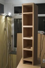
So back to the thread, with all the pieces now prepared it was time to dry fit everything and then get the screws in. This went reasonably well with the first cabinet (or so I thought), the tollerances were int he order of 1mm on the whole, nothing that can't be solved with some 40grit sandpaper and a bit of time However on closer inspection what I realised is that some of the braces had split slightly on one side as I did not pilot hole them (never believe what it says on the box of screws, always pilot home... not splitting my backside )
The second cabinet went much better and the fit was very good, helped by spending a bit more time on the alignment in the first place. It is all a learning curve, perhaps I should have made three cabinets to be on the safe side?!
This meant more measuring and drilling (and eventually filling), which leads me onto an aside:Why is it that building these speakers dominates my thoughts during the day and when I am trying to sleep like an obsession, however, when I am actually working on them my mind is elsewhere?
So back to the thread, with all the pieces now prepared it was time to dry fit everything and then get the screws in. This went reasonably well with the first cabinet (or so I thought), the tollerances were int he order of 1mm on the whole, nothing that can't be solved with some 40grit sandpaper and a bit of time
However on closer inspection what I realised is that some of the braces had split slightly on one side as I did not pilot hole them (never believe what it says on the box of screws, always pilot home... not splitting my backside )The second cabinet went much better and the fit was very good, helped by spending a bit more time on the alignment in the first place. It is all a learning curve, perhaps I should have made three cabinets to be on the safe side?!
Attachments
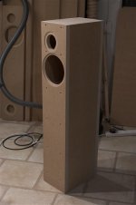
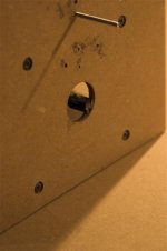
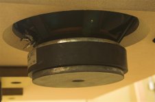
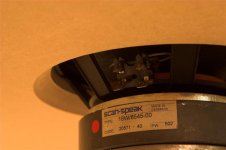
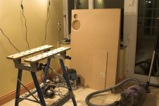
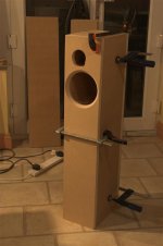
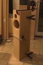
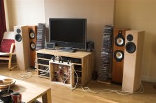
With a pair of cabinets now pieced together I couldn't resist getting the drive units fitted to see how they looked... then that lead to the thought that since I have a few days wait until the rest of the stuff arrives (port, stuffing, etc.) I might as well wire them up and have a listen. After a bit of digging in the shed to find my "old rag" collection, which is basically soft clothing past its best and some fabric I used for a parcelshelf many year ago I got something into the cabinets so they didn't sound too much like hollow boxes and some wires run into the cabinets. The latter of these was done using the hole you can see below filled by the speakon connector that will eventually populate it.
Attachments
I ended up going to bed around 1:30am after putting cd after cd in the player I was enjoying listening to them so much. In terms of clarity they are ahead of the Monitor Audios especially when it comes to the treble end of the spectrum, however, without the port they are lacking the weight and extension that I am used too. It is obviously unfair to do any serious reviews at this point, but early indications are very good.
I still have quite a bit to do with them, once the rest of the parts arrive they need stripping down, gluing, reassembling, damping and stuffing adding, wiring, terminal plate completing, veneering, plinth building... god that seems like a long list!
I still have quite a bit to do with them, once the rest of the parts arrive they need stripping down, gluing, reassembling, damping and stuffing adding, wiring, terminal plate completing, veneering, plinth building... god that seems like a long list!
Attachments
- Status
- This old topic is closed. If you want to reopen this topic, contact a moderator using the "Report Post" button.
- Home
- Loudspeakers
- Multi-Way
- Amish 45/97 Construction Diary