I'm assuming that 15A maximum is a typo, and that you really meant 1.5A?
If it isn't, then there's only really one way to do it DIY. You buy a tonking great transformer/rectifier/capacitor combination that will produce the required + and -60V dc, and power it from an equally large variac. If you don't need regulation, this is a really useful solution, particularly if (for example) you wanted a variable 0 - 600V supply capable of supplying 250mA at all voltages.
If you only need a comparatively fragile supply (1.5A), it's not too painful. Forget 3 terminal regulators. You need to go back to basics and make a regulator with an op-amp, a Darlington series pass transistor, a voltage reference, and a potentiometer. You will find that this is a standard circuit in all electronics books.
Refinements:
Voltmeters and ammeters, current limit, variable current limit.
Trouble is, unless you can find the big bits (transformer, rectifiers, capacitors, series pass transistors, heatsinks) for free, it will probably cost more than a commercial product.
JDeV,
I don't know if you really meant 15 amps or not.
In either case, with a linear power supply the biggest problem is power dissapation. Even at 1.5 amps it's horrendous with a simple setup.
Consider:
For 60v output max from the regulator, you'll need at least 65v going in, say 70v to be sure.
Now you decide to use the reg PS to give 5v at 1.5 amps.
The dissapation in the series pass transistor/IC will be 65*1.5=97.5 watts!. Or for 15 amps, nearly a killowatt!
There are ways round this:
What will you need most?
I suggest you might need 5 to 10 volts at high current. So make a section that does just that.
Probably you will want a supply that does 40 to 60 volts at a lower current. Make 2 of these, one for + and 1 for - rails.
Another way is to use a tapped transformer secondary (or many in series) and to switch the voltage available for the regulator.
A further way is to make a series of 5 volt regulators (all floating, and off their own secondary windings, and appearing on front panel banana sockets. Make all but 2 fixed 5v. Make 2 of them variable. You can then patch any voltage you want, and use IC regulators for up to 1.5 amps. There are protection considerations for series supplies that you would be well advised to discuss before embarking on this approach. But it is quite feasible.
Cheers,
* forget standard regulators
* make it a double 0...60V 15 A, not symmetrical
* it will be a huge project
- option 1 = Try fase-cutting the transformer on the primarie side true a opto-isolated loop that measures the over the voltage output stage and limits it to something about 10...15V. But you will also still have about 150W in heat that you have to get away with somehow, active cooling perhaps
- option 2 = use a very mucho power mosfet in the secundarie side and put it between the bridge and the buffer, thow i dont suggest this one for this amoint of power.
- option 3 = switching power supply, a lot cheaper, a lot smaller, a lot more difficult to design
- option 4 = instead of normal bridge operations, use 4 thyristors and build a nice uP based circuit for controlling timings.
forgot something ... these options are preregulators, they need to be followed bij a analog disigned regulator ( 2 opamps and 4 power transistors, with a seperated ps sow that they can work floating above the output voltage ), this way the beatiful creation can work in voltage source or current source, sometimes very usefull when testing circuits at that kind of power, couse when a circuit at 60V 15A goes down, it won't be the only thing that would be distroyed. ( edited )
A have created a power supply like option 1 and it works beatiful, its not completely done, i didnt build the display yet, wanted it lcd readout and digital controlling, but for the moments its all analog stuff, but heck maybe within a year i get bored with audio circuits and go back on the digital interface.
( my project for collage, circuit didnt work in those days thow ... )
)
pls think it all about 30 times over before starting and bying stuff for such a project.
Greetz Rudy
Good luck
* make it a double 0...60V 15 A, not symmetrical
* it will be a huge project
- option 1 = Try fase-cutting the transformer on the primarie side true a opto-isolated loop that measures the over the voltage output stage and limits it to something about 10...15V. But you will also still have about 150W in heat that you have to get away with somehow, active cooling perhaps
- option 2 = use a very mucho power mosfet in the secundarie side and put it between the bridge and the buffer, thow i dont suggest this one for this amoint of power.
- option 3 = switching power supply, a lot cheaper, a lot smaller, a lot more difficult to design
- option 4 = instead of normal bridge operations, use 4 thyristors and build a nice uP based circuit for controlling timings.
forgot something ... these options are preregulators, they need to be followed bij a analog disigned regulator ( 2 opamps and 4 power transistors, with a seperated ps sow that they can work floating above the output voltage ), this way the beatiful creation can work in voltage source or current source, sometimes very usefull when testing circuits at that kind of power, couse when a circuit at 60V 15A goes down, it won't be the only thing that would be distroyed. ( edited )
A have created a power supply like option 1 and it works beatiful, its not completely done, i didnt build the display yet, wanted it lcd readout and digital controlling, but for the moments its all analog stuff, but heck maybe within a year i get bored with audio circuits and go back on the digital interface.
( my project for collage, circuit didnt work in those days thow ...
)pls think it all about 30 times over before starting and bying stuff for such a project.
Greetz Rudy
Good luck
Commercial variable power supplies use multi-tap transformers to keep the voltage drop across the regulator transistors down. I use a BK Precision 1760 on my bench but it'll only do +/- 30V.
You're likely to be better off finding one that meets your needs on eBay; it'll probably be cheaper and will certainly have more features.
You're likely to be better off finding one that meets your needs on eBay; it'll probably be cheaper and will certainly have more features.
EC8010 said:I'm assuming that 15A maximum is a typo, and that you really meant 1.5A?
It started like this:
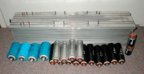
I got hold of a 1kVA 45-0-45 toroidal (AC rms values), 18 x 10000uF caps and a huge piece of heatsink (see pic). So I ask myself what to do with this now. Since I am interested in playing around with various amp. circuits, building a proper variable PSU seems like a good idea. I actually don't need a regulated PSU, but still investigated the possibility. I calculated that 1kVA should give me 60Vdc @ about 15A, that's where my specs come from. (Is it correct?) The main thing is that it must be adjustable. I am now bussy with an op-amp design which I think of using. Will post the circuit for opinions later.
Thanx for all advice and suggestions.
Attachments
Welding
That's a sizeable pile of ironmongery. If the transformer is 1kVA and has 45-0-45V secondary, then its maximum AC output current is 1000/90 = 11A. When you rectify and smooth, you draw your current in a series of high current pulses, and your capacitors charge to the peak voltage of the waveform leaving the rectifier. At this point, you really need to know what the transformer was designed for, but a reasonable guess for a continuous DC current rating is to divide the AC current rating by sqrt 2. All in all, you are probably good for 7A. Not quite what you had thought, but not to be sniffed at.
As you will have seen, all the posters have stressed the amount of power to be dissipated if you use a purely linear regulator, and Rudy has given a number of alternatives. All of the "proper" methods of making a variable, regulated supply are expensive. If you can do without regulation, go back to your inexhaustible supply of cheap kit, and buy a big variac. You will find this is also useful for soft starts on other kit.
When you rectify and smooth the output of your transformer, you will be dealing with very large currents indeed. The diodes will definitely need to be on a heatsink, and you will need really thick, short wires to the capacitors. In this instance, there is no such thing as too thick, or too short.
Re: Welding
 I can't help to start laughing, I suppose from an outside point of view it does indeed seems like if I got an "inexhaustible supply of cheap kit" If only I had some really usefull kit , like a VARIAC. It just happened that the company where I work where replacing some old equipment (printing industry) with new digital stuff, and I scored a couple of caps and some heatsink, in this case.
 ")
EC8010 said:If you can do without regulation, go back to your inexhaustible supply of cheap kit, and buy a big variac. You will find this is also useful for soft starts on other kit.
I can't help to start laughing, I suppose from an outside point of view it does indeed seems like if I got an "inexhaustible supply of cheap kit" If only I had some really usefull kit , like a VARIAC. It just happened that the company where I work where replacing some old equipment (printing industry) with new digital stuff, and I scored a couple of caps and some heatsink, in this case. JDeV said:I am now bussy with an op-amp design which I think of using. Will post the circuit for opinions later.
O.K. Here it is. Now you can start to stone me (or teach me). Just BTW, I am not qualified in any electronic trade/profession, so just keep it in mind before picking up some big rocks
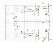
I quickly tried to use Simetrix and put together something that looks like a voltage regulator. I KNOW it is far from perfect and must be improved alot, but at least I tried. Although it is not really practical to use this method to adjust + and - 0-60V up to 15A, I will set the requirements to + and - 5-50V @ 5A, just for the exercise and to learn more about electronics - myself that is.Attachments
Rudy said:... that is not regulated ?
... or adjustable, at least?
It's a big rock, so I'll drop it gently...
There are rather a lot of things wrong with your proposed circuit. Let's start simple and work up to a space shuttle.
Fundamentally, a linear power supply is a non-inverting op-amp with an emitter follower added to increase its output current. It amplifies a voltage reference (often a 6.2V Zener), and its gain is adjustable, allowing the output voltage to be vared.
As shown, the circuit cannot go down to 0V, and is not protected against short-circuits, but it gives the general idea.
You need a book to help you. "A Practical Introduction to Electronic Circuits" by Martin Hartley Jones is very good.
Attachments
Re: It's a big rock, so I'll drop it gently...
I think that rock was made of sandstone, landed very softly
O.K. I got some more odds and ends on PSU's and op-amps from internet and will study them and do some mods. to my circuit (I learn much better by practically trying then by just reading a book - so I hope Simetrix will give me some usefull results)
A question: Is it possible to use zeners (in practice) for + and - supply to op-amp (in this case OPA501 must have min. +- 10v up to max. +- 40v) if your supply are way too high for op-amp supply?
EC8010 said:There are rather a lot of things wrong with your proposed circuit. Let's start simple and work up to a space shuttle.
Fundamentally, a linear power supply is a non-inverting op-amp with an emitter follower added to increase its output current. It amplifies a voltage reference (often a 6.2V Zener), and its gain is adjustable, allowing the output voltage to be vared.
As shown, the circuit cannot go down to 0V, and is not protected against short-circuits, but it gives the general idea.
You need a book to help you. "A Practical Introduction to Electronic Circuits" by Martin Hartley Jones is very good.
I think that rock was made of sandstone, landed very softly
O.K. I got some more odds and ends on PSU's and op-amps from internet and will study them and do some mods. to my circuit (I learn much better by practically trying then by just reading a book - so I hope Simetrix will give me some usefull results)
A question: Is it possible to use zeners (in practice) for + and - supply to op-amp (in this case OPA501 must have min. +- 10v up to max. +- 40v) if your supply are way too high for op-amp supply?
Re: Re: It's a big rock, so I'll drop it gently...
Yes, but it means adding a gain stage after the op-amp, and when you apply the feedback, there is a very real danger of it oscillating. It's probably easier to make your own op-amp out of a cascade of differential pairs using hgher voltage transistors. If you get yourself a breadboard, you can knock up circuits quickly and easily.
You really would be better off with a variac. This isn't going to be easy at all.
JDeV said:Is it possible to use zeners (in practice) for + and - supply to op-amp (in this case OPA501 must have min. +- 10v up to max. +- 40v) if your supply are way too high for op-amp supply?
Yes, but it means adding a gain stage after the op-amp, and when you apply the feedback, there is a very real danger of it oscillating. It's probably easier to make your own op-amp out of a cascade of differential pairs using hgher voltage transistors. If you get yourself a breadboard, you can knock up circuits quickly and easily.
You really would be better off with a variac. This isn't going to be easy at all.
another way of making a supply
I'm working on a bench PSU for testing power-amps. I based my design on an old Elektor Electronics design that provides 2*25V/2.5A. Two of those makes +/- 50V/2.5 A. Thats enough for testing most amps.
Some designs needs a seperate supply for the voltage amplifiers and for that purpose I put two 0-15V/0.5A in the case also.
The total heat-disap. should be around 200W, and with a couple of fans it should not be a problem.
I'll post pics later
(please Xcuse my bad english)
Troels
- Status
- This old topic is closed. If you want to reopen this topic, contact a moderator using the "Report Post" button.
- Home
- General Interest
- Everything Else
- Bench PSU circuit