Has anyone played with 6GV8 at voltages of less than say 100V? The pentode curves look nasty in that range of plate voltages but all of the graphs are with screen voltages around 200V. I wonder how they would work with lower screen voltages or triode strapped. Thinking something like 80V on plate and 60V on the screen.
mike
mike
Hi,
I know this is an old post but this might help a little. Silicon Chip Online - Vintage RadioSilicon Chip Online - Vintage Radio
I know this is an old post but this might help a little. Silicon Chip Online - Vintage RadioSilicon Chip Online - Vintage Radio
Attachments
G'day Mike,
You are probably aware that 6GV8 = ECL85, so you can look for ECL85 schamatics and data.
The Pentode curves do indeed look pretty nasty at low Va. Most of the application data I've seen runs 170V anode and screen.
Might be interesting to try them in limiting Class A Push Pull.
The triode section however looks resonable at lowish voltages.
Cheers,
Ian
Hi GingerTube,
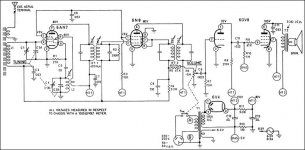
The Kreisler radio schematic i've posted, as an OT value at 3300 ohm. However is that a bit high?
Using Z = Va^2 / Pa , where pa is 9 watts gives
Z=110^2 /9
Z=1344
if an 8 ohm speaker load was used on the 15 ohm output then it would reflect 1650 ohms , a much closer match.
I'm wondering if a low bias of 5v was used to compensate for the high Z . It looks difficult to calculate the correct bias form the data sheet a the low voltage of 110. Besides the curves are not published for 110v only for 170v.
Could a hight bias say 5v-10v be a better bias . considering that the bias for 170v a 3500 ohm is 15v from the data sheet. Would a higher than usual z be used to reduce the output to match the power ratings of the 4' speaker? or perhaps they were the only Ot's that were close?
I'm curious as i have a few of these that i can play around with and am looking to increase the performance of the amp
Cheers
Neil
Last edited:
Neil,
The ONLY SE Audio Output data I can find for the pentode section says:
Va, Vg2 = 170 Volts
Ia = 41 mA
Vg1 = -15V
Output Transformer primary Impedance = 4K
Output Power 3.4 Watts
At that working point the internal impedance (rp) of the pentode section is around 25 K Ohms.
Some folk have trouble understanding this large internal impedance (25K) vs the output transformer reflected impedance (4K) . I just think of it as the pentode acting as a current source, driving current through the transformer primary.
At lower Va in the Kriesler circuit we can't get as much voltage swing and so they lowered the primary impedance a bit to 3K3, to swing similar audio signal current at lower voltage swing.
At Va = 110V and Vg2 of 80 or 90V the idle current would be much lower and so the Vg1 was reduced from -15V to -5V.
Note with the datasheet values you have 170V x 41mA = 7 Watts anode dissipation which is right on the limit. At Va = 110V you can afford to run the idle current up around 60mA rather than 41mA and that also accounts for the large change in bias voltage from -15V down to -5V.
Did'nt follow your power calculation at all.
Try it this way.
For 3.4 watts out (ignoring transformer losses) you need 3.4 watts delivered into the 3K3 primary (use 3.3 Watts to simplify calc).
From Power = Current squared x impedance
3.3 = I^2 x 3300
I^2 = 1/1000
I = 0.032 mA RMS (This is the audio signal current swing through the primary).
That is about 45 mA pk or 90 mA peak to peak.
Now that means the idle current must be at least 45mA so it can swing down to 0 and up to 90 mA.
The datasheet gm is 7.5 mA/V. At a bias of -5V you can only get 10V pk-pk swing at the grid, so only 75mA swing into the OT. So you are not going to get 3.4 Watts, probably more like 2 to 2.5 Watts. Plenty for a mantle radio.
That is a rough calc. - you can repeat if you want. (allow OT losses of 10%).
There are also othet ways of looking at the output tube / output transformer combination, this way just works for me when looking at SE output stages.
Cheers,
Ian
Hi GingerTube,
Its taken me a while to get back to this
Z = Va^2 / Pa is a rule of thumb suggested from, http://valvewizard1.webs.com/se.html.
Pa should be 7 ( not 9) , So ( rule of thumb ) Z = 110^2 / 7
= 1728
So On that basis it would seem that an 8 ohm speaker attached to the 16 ohm tap , the primary being 3300 would reflect 1650. a good match.
if ~100v passes through the OT 100 /1650 gives ~ 60ma as you suggest
I have found the http://www.tubes.mynetcologne.de/roehren/daten/ecl85pentode_100v.pdf that shows curves for screen at 100v.
I have changed the bias to be cathode biased , with 180R. that gives -7v
But I'm confused if have actually picked the right bias point for the operating conditions?
Cheers
Neil
- Status
- This old topic is closed. If you want to reopen this topic, contact a moderator using the "Report Post" button.
- Home
- Amplifiers
- Tubes / Valves
- 6GV8 at lowish voltage