Im looking into getting the 6550s to run with DC to get hold off some hum issue. i have dual 6.6V ac windings at 5 amps now at the PT. has anyone a simple and reliable cct to do this? im thinking of a std 3810 bridge diode pack for this and a cap of say 10,000uF and some dropper resistors to keep it simple.
hey-Hey!!!,
I doubt your hum issue is from power tube AC heating. There are waaaay too many amps around, that run quietly with their power finals AC heated( DH included ) for that to be likely...
Also, a cap-input filter capable of delivering that sort of current is going to increase your risk for noise elsewhere due to huge current deliveries to that filter when the diodes are conducting.
Look to gounding. Is the OPT secondary ref'd to ground, and how about the heaters?
cheers,
Douglas
Got to agree with Doug on this one, it is far more likely that the hum issues arise due to construction details that aren't quite right or a design issue.
The signal levels are so high in the output stage and with the 6550 the cathodes are reasonably well isolated from the filaments so this is very unlikely to be a significant path of hum injection.
Badly executed filament wiring however could be the culprit. Are your filament lines twisted and arranged to minimize loop area around the sockets, are they routed well clear of low level circuitry and passive parts in the audio path? Are the filaments driven by a center tapped filament winding or have you created a pseudo center tap with with resistors? Both good solutions, floating or grounded to one leg are likely to create hum issues.
Is it hum or buzz? 60Hz vs. 120Hz or 180hz?
How is internal grounding in the amplifier implemented? Single common ground point to chassis, ground bus or ?
Is this a diy amp, current offshore production, vintage or ?
Output transformers placed too close to the power transformer, and/or not oriented for minimum magnetic pick up?
Global feedback or not?
Sorry for all of the questions!
Can you provide pictures and schematics of your amplifier - it would help in giving you some helpful answers.
Do you have a scope? Other test equipment that might help in tracking down the root cause?
Got to agree with Doug on this one, it is far more likely that the hum issues arise due to construction details that aren't quite right or a design issue.
The signal levels are so high in the output stage and with the 6550 the cathodes are reasonably well isolated from the filaments so this is very unlikely to be a significant path of hum injection.
1 - Badly executed filament wiring however could be the culprit. Are your filament lines twisted and arranged to minimize loop area around the sockets, are they routed well clear of low level circuitry and passive parts in the audio path? Are the filaments driven by a center tapped filament winding or have you created a pseudo center tap with with resistors? Both good solutions, floating or grounded to one leg are likely to create hum issues.
2 - Is it hum or buzz? 60Hz vs. 120Hz or 180hz?
3 - How is internal grounding in the amplifier implemented? Single common ground point to chassis, ground bus or ?
4 - Is this a diy amp, current offshore production, vintage or ?
5 - Output transformers placed too close to the power transformer, and/or not oriented for minimum magnetic pick up?
6 - Global feedback or not?
Sorry for all of the questions!
Can you provide pictures and schematics of your amplifier - it would help in giving you some helpful answers.
Do you have a scope? Other test equipment that might help in tracking down the root cause?
Thks all, for yr inputs. OK i shall look else where to nail the hum.
1 - on the 6.6Vac line i ran 100ohm res each leg to GND. virtual GND as i do not have CT on the windings. no difference in hum even if removed.
2 - i do not have a osilo, but it seems to hum 60hz low bassy and loud. sometimes as the 6550s are heated up i get an added on 120hz i think as its sharper buzz. inputs shorted to GND, i did a chopstick whack on the PS module i built and it seems to have an effect. i am now dismantling the PS to both beef up and make it sturdier.
3 - i broke the GND schema to 2 star points by cutting the pcb tracks. first star is from the PS first cap -ve, connecting 6550 cathodes and grid (cathode biased), 6.6Vac, wall earth, OPT gnd. second star connects invertor, input stage and the RCA pin gnd. then another wire links star 1 and 2located 1.5 feet away.
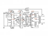
4 - its a jadis 30 based design pcb as attached.
5 - the whole thing is now screwed onto a wooden board 1ftx3ft. at the fartherst ends of the board are the input section 12AU7 and the PT the other. so OPT and PT are about 2ft 90deg off.
6 - no GFB as the 20k//100pF combination gave blurr music...no treble
i think part of the problem is the wooden board itself and there is no metal plates around to shield RF and such. im also in the midst of getting the metal work done parallel but feeling fristrated as well with such loud hum with input shorted. will post pics.
thks and cheers
Attachments
Get those 510k grid resistors down to 220k before it will run away out of the blue. The blur is because your OPTs are not Jadis and the comp cap parallel to the GNFB 20k res is probably over compensating. Get an oscope and check 10kHz squares. Till then try to use a smaller cap by ear but close the loop. Your hum problem is 90% odds grounding issue.
Get those 510k grid resistors down to 220k before it will run away out of the blue.
Hi Salas, thks for the input. im not clear what is the difference between the 510k and 220k grid resistors. is this a safety issue here ("run away out") that they need to be changed? BTW im on 6550 (not the KT88 as in diagram).
OK the OPT is the Hammond 1650R, 5k p=p, 318ma max.
PT is 500mA, 420Vac secondary and the rest ie 6.6vacX2, 5A and 15Vac etc
cheers
Thks all, for yr inputs. OK i shall look else where to nail the hum.
1 - on the 6.6Vac line i ran 100ohm res each leg to GND. virtual GND as i do not have CT on the windings. no difference in hum even if removed.
2 - i do not have a osilo, but it seems to hum 60hz low bassy and loud. sometimes as the 6550s are heated up i get an added on 120hz i think as its sharper buzz. inputs shorted to GND, i did a chopstick whack on the PS module i built and it seems to have an effect. i am now dismantling the PS to both beef up and make it sturdier.
3 - i broke the GND schema to 2 star points by cutting the pcb tracks. first star is from the PS first cap -ve, connecting 6550 cathodes and grid (cathode biased), 6.6Vac, wall earth, OPT gnd. second star connects invertor, input stage and the RCA pin gnd. then another wire links star 1 and 2located 1.5 feet away.
4 - its a jadis 30 based design pcb as attached.
5 - the whole thing is now screwed onto a wooden board 1ftx3ft. at the fartherst ends of the board are the input section 12AU7 and the PT the other. so OPT and PT are about 2ft 90deg off.
6 - no GFB as the 20k//100pF combination gave blurr music...no treble
i think part of the problem is the wooden board itself and there is no metal plates around to shield RF and such. im also in the midst of getting the metal work done parallel but feeling fristrated as well with such loud hum with input shorted. will post pics.
thks and cheers
Sounds like you did the right thing with the filaments.
I am confused about your star ground comment. Is the whole thing built on a wood base or is there a metal chassis? If metal, there should be only one point connected to the chassis.
As described it seems likely that you are getting hum pick up by virtue of the way the thing is built. It should be built in a sturdy metal box which will shield all of the signal path from external capacitive pick up issues. The wood base provides no shielding at all.
If you are going to be building amplifiers you really need a modest scope for audio work, one having a calibrated time base, and a vertical bandwidth of 10MHz minimum.. Delayed sweep and 2 or more vertical channels with bandwidth of >20MHz is a lot better, and probably not that costly if you shop carefully on eBay. A basic function generator, and a good dvm will allow you to figure most things out with a minimum of difficulty.
Long ago (10+ yrs ago) I used to service Jadis amplifiers particularly the Defy 7 and some of the monoblocks. (model #s forgotten, but mostly higher powered models)
These amplifiers have a marked tendency to blow up. Some of it was just due to the quality and inadequate ratings of the components used. Some of it is due to deliberate and IMO poor design choices.
Salas is right about the 510K resistors on the grids of the 6550, this can result in runaway and destruction of the output tubes. I've seen this happen repeatedly in Jadis amps. Unfortunately due to the very questionable choice of a 12AX7A as the driver you can't drive low impedances effectively. Reducing this resistor to 220K will reduce loop gain significantly. Don't even think of triode connecting the outputs because the 12AX7A cannot handle the miller capacitance that results.
Overall this idiosyncratic design just is not a very good one. Much better would be to use the 12AX7A in the first stage and a 12AU7A or better still 12BH7A in the second stage. These amplifiers can sound nice, but IMO are nothing more than a high power "tone control" - they are not accurate. Your comments about the lack of treble with the feedback connected are what I would expect from these amps with an average Hammond OPT (the Jadis opts actually are rather good - the saving grace in these amplifiers.) and you have what you describe.
Placing 3K of resistance in series with the 6550 screens is excessive, a few hundred ohms should be about the upper limit.
Last edited:
hey-Hey!!!,
There are published limits on grid circuit resistance. This is because there is a bit of grid current, and it must not be able to disrupt the grid voltage( through the resistance ) in any significant way. The 6550 is a high gm tube, and IIRC it was spec'd for maximum grid circuit resistance of 250k in cathode bias. You'd be at 2x that with the 510k...waaaaaay to high IME. Besides, the power tubes wind up sounding better with less resistance there anyway.
cheers,
Douglas
Hi Salas, thks for the input. im not clear what is the difference between the 510k and 220k grid resistors. is this a safety issue here ("run away out") that they need to be changed? BTW im on 6550 (not the KT88 as in diagram).
OK the OPT is the Hammond 1650R, 5k p=p, 318ma max.
PT is 500mA, 420Vac secondary and the rest ie 6.6vacX2, 5A and 15Vac etc
cheers
Yes its not safe. Explanation covered by the other members.
Your Hammond is a ''slow'' one, can't use the same compensation cap as from original, especially if you get your grid leaks down to 220k. I agree with kevin, its better to modify. 12AX7's can't push treble if you go down on the grid resistors. Well, they cant push 6550's anyway.
") Have a look at a reasonable way of handling those tubes for driving KT88/6550. The example is the GEC 50W classic.
Have a look at a reasonable way of handling those tubes for driving KT88/6550. The example is the GEC 50W classic.Attachments
Is the published 30kHz bandwidth a typo?
EDIT. Searched about a bit, and I have seen that an analogous Lundahl 1679 (105W 4.5K P-P UL taps) is quoted 70kHz, that is a double C core. Also a Hashimoto HW-100-5 (Double C type?) shows a chart with -3dB at 80kHz without a primary impedance resonance somewhere, though it is an expensive unit. Those are claims of course and I don't know what happens when they get stressed.
Its nice to know that the 1650R can do fine, because good OPTs tend to cost an arm and a leg these days. Surely we can not expect any compensation scheme found in an original schematic that worked with some certain and sometimes dedicated transformer to work for any other. Our friend needs an oscope, a gen, and some 10kHz squares to tune whatever assortment he ends up with.
Im looking into getting the 6550s to run with DC to get hold off some hum issue. i have dual 6.6V ac windings at 5 amps now at the PT. has anyone a simple and reliable cct to do this? im thinking of a std 3810 bridge diode pack for this and a cap of say 10,000uF and some dropper resistors to keep it simple.
Before you spend the time and $$ to build a DC supply try powering the heaters with a battery. A few D cells will do it. If that kills the hum then go for it but if you still have hum with the battery supply then the heaters are not yor problem.
Recently I had a hum problem that did turn out to be the hearer supply. I was letting the voltage float. I made a "artificial center tap" using two 100R resisters to ground and the preamp was them silent.
OK if you do build a big DC supply place the dropper resisters _between_ a two large caps where they can do some double duty as both dropping and filtering. Use a two or even three stage filter.
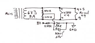
My hunch is, there is a ground loop. AC heating gives absolutely no hum in my 95dB speakers driven by my 31dB gain KT88 20W trioded amp. Dead silent background for hiss also. Its very cramped inside, sporting a 250VA toroid underneath, smack centre. If it can be done like this (took some careful experimentation), it surely can be done easily when space is normal and PTX can be located logically away from signal wiring and sensitive gnd nodes, above a metal top plate. Had to do it in a small chassis as I used a donor one from a Serbian amp that I disassembled but kept the Audio Note OPTs. I had no space for DC heating regulators even for the 12AY7s and 12AT7s. Here is the way I heat it up. It may be of help.
Attachments
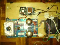
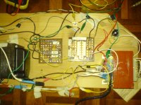
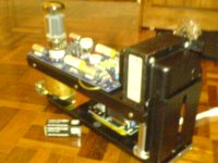
hi all, thks very much for all the valuable inputs in improving this (esp. Kevin and Salas). here i have is the wooden testbed im using now. the input stage 12AU7 is being sheilded by a cake alu can. you can also see the 2 star points for the 12AU/AX and another for the 6550 only. there is also a DC heater module for the AU/AX.
as i read the inputs, it makes sense to move towards Sala's GEC50W cct. so since its a PCB based to start with, im trying to figure the best way to cut up the tracks and reconfig to accommodate the AX->AU->6550->1650R40UL rather than the current AU->AX->6550->1650R40UL.
cheers
as i read the inputs, it makes sense to move towards Sala's GEC50W cct. so since its a PCB based to start with, im trying to figure the best way to cut up the tracks and reconfig to accommodate the AX->AU->6550->1650R40UL rather than the current AU->AX->6550->1650R40UL.
cheers
Attachments
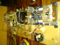
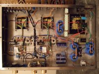
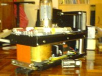
here is the mock up of the actual build. its a dual deck metal frame. lower deck has PT, DC heater reg and HT modules for 6550/AU-AX. upper deck has hammond 1650R and PCB. the whole thing measures up 7in width, 15in length and height about 10in or so depending on the 6550 ceiling. its quite a compact build.
cheers
cheers
Hey! You wonder why you have hum! The pics say the whole story.
Don't even bother to fix it in this style. Seriously.
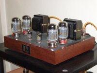
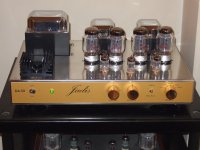
You are making a Jadis 30 clone. My neighbor has a DA-30. Look at the photos from when I got it here to listen to it and put a couple of Black Gates in. See how it is made?
Punch a nice roomy metal box for power octals and driver novals, set your output transformers atop, set your power transformer with reverse orientation amongst them. Read about star and buss bar grounding, test some suitable for classic 3 stage noval + octal schematics point to point. Look to the many photos here in the DIY tube gallery. See how people are wiring them up and grounding them.
Don't even bother to fix it in this style. Seriously.
You are making a Jadis 30 clone. My neighbor has a DA-30. Look at the photos from when I got it here to listen to it and put a couple of Black Gates in. See how it is made?
Punch a nice roomy metal box for power octals and driver novals, set your output transformers atop, set your power transformer with reverse orientation amongst them. Read about star and buss bar grounding, test some suitable for classic 3 stage noval + octal schematics point to point. Look to the many photos here in the DIY tube gallery. See how people are wiring them up and grounding them.
Attachments
here is the mock up of the actual build. its a dual deck metal frame. lower deck has PT, DC heater reg and HT modules for 6550/AU-AX. upper deck has hammond 1650R and PCB. the whole thing measures up 7in width, 15in length and height about 10in or so depending on the 6550 ceiling. its quite a compact build.
cheers
pardon me,the pictures did not upload the first time, so here it is.
Attachments
- Status
- This old topic is closed. If you want to reopen this topic, contact a moderator using the "Report Post" button.
- Home
- Amplifiers
- Tubes / Valves
- DC filaments for 6550s