Member
Joined 2009
Paid Member
Please forgive me if this is old news, it's my first post to the Tubes forum and I'm unfamiliar with Tubes and their history. I've tried a search for "Tube FET CFP" and got nothing.
I'm interested in the idea of a SE Triode amplifier. I've never made one (or heard one) but there is a legend around the SET that intrigues me.
Trouble is, I'd like more output power and perhaps the option of a lower damping factor. I'm willing to make some compromises on the sound to achieve this - for example, by going OTL.
I thought perhaps I could use a MOSFET as a 'slave' to the Triode in a complimentary feedback pair arrangement (CFP).
This arrangement keeps a fairly constant current through the Triode and allows the Triode to offload the dirty job of flowing lots of current to a MOSFET.
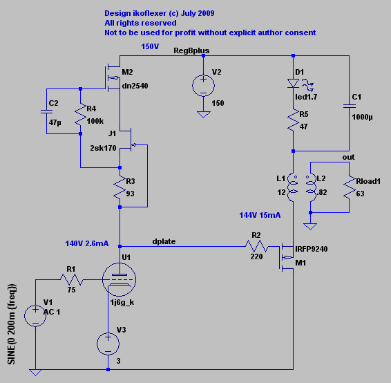
I used Nelson Pass zen v4 amplifier as the basic building block for this purpose.
Note that my knowledge of tubes is limited, the one I show in the schematic was chosen simply because my friends Chines hybrid amp uses it and I had an old simulation file already that had a custom spice model in place already.
Question - has this been tried before (if yes and it worked, can you point me to where I can get further information) ?
I'm interested in the idea of a SE Triode amplifier. I've never made one (or heard one) but there is a legend around the SET that intrigues me.
Trouble is, I'd like more output power and perhaps the option of a lower damping factor. I'm willing to make some compromises on the sound to achieve this - for example, by going OTL.
I thought perhaps I could use a MOSFET as a 'slave' to the Triode in a complimentary feedback pair arrangement (CFP).
This arrangement keeps a fairly constant current through the Triode and allows the Triode to offload the dirty job of flowing lots of current to a MOSFET.
I used Nelson Pass zen v4 amplifier as the basic building block for this purpose.
Note that my knowledge of tubes is limited, the one I show in the schematic was chosen simply because my friends Chines hybrid amp uses it and I had an old simulation file already that had a custom spice model in place already.
Question - has this been tried before (if yes and it worked, can you point me to where I can get further information) ?
Attachments
Last edited:
What I meant was that your circuit reminds me of a mu-follower, even though those that I have seen have been for low current driver applications:
http://www7.taosnet.com/f10/mustage.html
http://www.tubecad.com/june2000/page10.html
I think Gary Pimm proposed an output-capable mu-follower on his interesting site. Have a search around... http://www.pimmlabs.com/
http://www7.taosnet.com/f10/mustage.html
http://www.tubecad.com/june2000/page10.html
I think Gary Pimm proposed an output-capable mu-follower on his interesting site. Have a search around... http://www.pimmlabs.com/
Hello Bigun,
Yes, somewhat similar ideas have been around on the tube forum. The complementary current driver on top is approx. similar to a version of what has been called anti-triode. The Sziklai combo on the bottom has often been mentioned loosely as a Darlington variant.
Usually the current multiplication function has been discussed using a Bipolar part with near constant Beta rather than a Mosfet. The Mosfet non-linear V to I transfer function will dilute the triode sound. A bipolar transistor however has DC/thermal stability problems of course when loaded by an xformer (low DC resistance) or low Z speaker.
Not sure if any real amplifiers other than exploratory tests have been executed. I would start by searching on anti-triode and Darlington, also Sziklai (but often miss-spelled) in the tubes forum. I have also heard of a relatively recent patent for a tube/SS Sziklai combo. (yes, quite annoying to see old patents re-patented) Also another patent was mentioned for a SS current multiplying current mirror load for tubes.
These are some of the posters with ideas related to this, just off the top off my head, no doubt there are others:
smoking-amp
kenpeter
michael koster
tubelab
wavebourn
revintage
Don
Last edited:
Hi Bigun;
I've been following this path for a while; looking at your schematic I can say that what you have to think about, is how to prevent thermal run-away. I've made one running amp such a way, but it was not an easy task: I burned lot of high power resistors and MOSFETs until figured out how to protect them from making harakiri.
Also, making a triode with such huge transconductance think of an equally huge Miller capacitance.
You might want to check this out: http://www.tubelab.com/SuperTubeSE.htm as well
Please forgive me if this is old news, it's my first post to the Tubes forum and I'm unfamiliar with Tubes and their history. I've tried a search for "Tube FET CFP" and got nothing.
I'm interested in the idea of a SE Triode amplifier. I've never made one (or heard one) but there is a legend around the SET that intrigues me.
Trouble is, I'd like more output power and perhaps the option of a lower damping factor. I'm willing to make some compromises on the sound to achieve this - for example, by going OTL.
I thought perhaps I could use a MOSFET as a 'slave' to the Triode in a complimentary feedback pair arrangement (CFP).
This arrangement keeps a fairly constant current through the Triode and allows the Triode to offload the dirty job of flowing lots of current to a MOSFET.
I used Nelson Pass zen v4 amplifier as the basic building block for this purpose.
Note that my knowledge of tubes is limited, the one I show in the schematic was chosen simply because my friends Chines hybrid amp uses it and I had an old simulation file already that had a custom spice model in place already.
Question - has this been tried before (if yes and it worked, can you point me to where I can get further information) ?
I have built and tested a few complementary current push-pull amplifiers and
continue to pursue the design.
Here is a series version like yours but without the current multiplier on the tube:
http://www.diyaudio.com/forums/showthread.php?t=128950
and here is a parallel version using an op-amp driving a MOSFET:
http://www.diyaudio.com/forums/showthread.php?t=118725
Nice use of the BJT in your mirror circuit to increase open-loop gain; good for low
impedance use. For high impedance, using an OPT, a simple cascode seems
to work well.
Cheers,
Michael
Member
Joined 2009
Paid Member
Wow, thanks everyone, the Tubes Forum was clearly the right place to start with ! - I'm busy reading and following-up on the links you've posted for me.
Gordy - thanks for the advice. The term 'mu-follower' is (was) unfamiliar to me. Those were handy links and there's quite a bit for me left to read. The first one is very encouraging about the approach I've taken with a MOSFET CCS on top of the Triode. If I understand correctly, 'mu' is different from transconductance and transistor beta, but defines for an active device the voltage gain achieved at a fairly constant current ?
Smoking-amp - I have never used MOSFETs before, only BJTs so it would have been my first choice as you suggested. The reason I didn't use BJTs for this proposed design is because with a standing idle current of 2A required there would be a considerable bass current of 20mA. This base current would translate into a higher current through the Triode. I assumed that this is too much to expect of an amplifying tube. Since this is a single stage amplifier (aka Zen) I don't have the 'luxury' of using separate amplifying and power stage tubes.
The MOSFET has negligible dc gate current requirements. It's disadvantage is the rising load presented by it's gate capacitance, which will result in an early high-frequency roll-off I have to live with. I'm not too concerned, my only and first amplifier project was an all BJT ClassAB amplifier and there you need good high frequency performance so that the negative feedback can take care of cross-over distortion. I don't expect to need that for the Triode-FET amp. Does this make sense ?
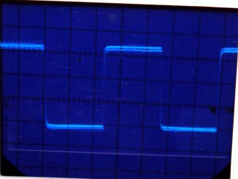
Ikoflex - thanks for sharing your design, it certainly helps to see some good results presented; square wave looks great, what frequency was it tested at?. In your design you have an output transformer. This is something I decided not to use - mostly because it's another piece of technology I'm unfamiliar with, but also size, weight and cost and deciding on what specifications are needed. I noticed that if you could use a BJT somewhere you'd have every kind of active device represented in your amp !
Miles - that's a great link, looks to me like a SS transistor in Complimentary Feedback Pair arrangement with a Tube. Very encouraging. It has taken the path of being two-stage. Interesting that the author makes the statement "Mosfets do not have the SOA limitation, but so far I have obtained better sound with bipolar devices." - not sure I can do much about this since I don't believe I can use a Bipolar device unless I go the next step and make it a Darlington to reduce the standing bass current draw from the Triode ? Unfortunately Super Tube has stopped work on that project.
Michael - The Spud-Assist looks great! OK, so it's got different goals than my proposal in that you employ an output tube but the simplicity of your circuit is what I'm seeking. But I am seeking to eliminate the output transformer and achieve higher output powers - essentially limited only by my appetite for heatsinks. Both of the links you posted mention 'push-pull'. It's true that my proposed design uses a modulated CCS at the top, but the intent was not to achieve push-pull operation. In fact, the design should be functional without any modulation of the CCS. This CCS design originates from Nelson Plass Zen amp (actually Aleph, but I digress) as a means to reduce distortion. In reality the value of this for me is that I can adjust the amount of CCS modulation as a % of the output signal and change the distortion profile of the amplifier to 'suit my ears'. Maybe it's all the same thing in the end ? So I did a search for 'anti-triode' and now I see the connection is well known.
So what next ? - I think I'm going to build an all SS version into an old power supply box first off to gain some experience with this simple topology. In parallel I want to refine the Triode version. I have been generously offered a source of Triodes today.
The 'big question' remains, how much of the Triode's character will survive the vice-like grip of the CFP Mosfet ?
Gordy - thanks for the advice. The term 'mu-follower' is (was) unfamiliar to me. Those were handy links and there's quite a bit for me left to read. The first one is very encouraging about the approach I've taken with a MOSFET CCS on top of the Triode. If I understand correctly, 'mu' is different from transconductance and transistor beta, but defines for an active device the voltage gain achieved at a fairly constant current ?
Smoking-amp - I have never used MOSFETs before, only BJTs so it would have been my first choice as you suggested. The reason I didn't use BJTs for this proposed design is because with a standing idle current of 2A required there would be a considerable bass current of 20mA. This base current would translate into a higher current through the Triode. I assumed that this is too much to expect of an amplifying tube. Since this is a single stage amplifier (aka Zen) I don't have the 'luxury' of using separate amplifying and power stage tubes.
The MOSFET has negligible dc gate current requirements. It's disadvantage is the rising load presented by it's gate capacitance, which will result in an early high-frequency roll-off I have to live with. I'm not too concerned, my only and first amplifier project was an all BJT ClassAB amplifier and there you need good high frequency performance so that the negative feedback can take care of cross-over distortion. I don't expect to need that for the Triode-FET amp. Does this make sense ?
Ikoflex - thanks for sharing your design, it certainly helps to see some good results presented; square wave looks great, what frequency was it tested at?. In your design you have an output transformer. This is something I decided not to use - mostly because it's another piece of technology I'm unfamiliar with, but also size, weight and cost and deciding on what specifications are needed. I noticed that if you could use a BJT somewhere you'd have every kind of active device represented in your amp !
Miles - that's a great link, looks to me like a SS transistor in Complimentary Feedback Pair arrangement with a Tube. Very encouraging. It has taken the path of being two-stage. Interesting that the author makes the statement "Mosfets do not have the SOA limitation, but so far I have obtained better sound with bipolar devices." - not sure I can do much about this since I don't believe I can use a Bipolar device unless I go the next step and make it a Darlington to reduce the standing bass current draw from the Triode ? Unfortunately Super Tube has stopped work on that project.
Michael - The Spud-Assist looks great! OK, so it's got different goals than my proposal in that you employ an output tube but the simplicity of your circuit is what I'm seeking. But I am seeking to eliminate the output transformer and achieve higher output powers - essentially limited only by my appetite for heatsinks. Both of the links you posted mention 'push-pull'. It's true that my proposed design uses a modulated CCS at the top, but the intent was not to achieve push-pull operation. In fact, the design should be functional without any modulation of the CCS. This CCS design originates from Nelson Plass Zen amp (actually Aleph, but I digress) as a means to reduce distortion. In reality the value of this for me is that I can adjust the amount of CCS modulation as a % of the output signal and change the distortion profile of the amplifier to 'suit my ears'. Maybe it's all the same thing in the end ? So I did a search for 'anti-triode' and now I see the connection is well known.
So what next ? - I think I'm going to build an all SS version into an old power supply box first off to gain some experience with this simple topology. In parallel I want to refine the Triode version. I have been generously offered a source of Triodes today.
The 'big question' remains, how much of the Triode's character will survive the vice-like grip of the CFP Mosfet ?
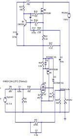
"The 'big question' remains, how much of the Triode's character will survive the vice-like grip of the CFP Mosfet ? "
You could try a technique I use (and probably used by a few others too) that takes the Mosfet transfer characteristic out of the equation: Replace the U1 triode with a pentode, replace R3 with a current source set at the idle tube current, and use a zener to drop the voltage from the M2 source down sufficiently to power the g2 screen grid of the pentode.
The g2 grid acts like the feedback terminal for a normal triode, so it servos the Mosfet output to get its Mu (g2/g1 Mu) satisfied on g2. This also operates the g2/g1 triode at constant current for low distortion. Since g2 and plate track each other, there is near linear variation in the screen current as it intercepts a constant fraction of cathode/plate current.
The downside is that output voltage swing will be constrained to the operating range of the g2 grid. But for a direct output setup (no output xfmr) as you have, this should not be a problem.
Another variant would use an additional Mosfet above the existing triode in cascode to emulate the pentode connection described above. (feedback then to the cascode gate = g2 above) This might be more esthetically pleasing for some to have an actual triode in the unit, and allows for tube rolling to try different triode sounds.
Don
Ikoflex - thanks for sharing your design, it certainly helps to see some good results presented; square wave looks great, what frequency was it tested at?. In your design you have an output transformer. This is something I decided not to use - mostly because it's another piece of technology I'm unfamiliar with, but also size, weight and cost and deciding on what specifications are needed. I noticed that if you could use a BJT somewhere you'd have every kind of active device represented in your amp !
We might have different objectives, but I thought it's good to see another variation that seems to work actually. I have a thread on that; I started quite complicated, with a ccs output, and wanted to avoid a transformer output by all means. In the end the lowest distortion came from the circuit above. The square wave was at 1kHz.
Regarding your last question, I too hope to not lose that sound of the triode, trying to use the mosfet in the least damaging way possible.
Bigun,
The other posters are much more versed in the type circuity you're interested in than I am. However, you did mention a 20 mA. "idle" current. The 12B4 is a linear low μ triode that needs such an idle current to sound good.
The amplification factor (μ) of a triode is directly related to its geometry. The 3 small signal parameters: μ, transconductance (gm), and plate resistance (RP) are associated with the equation that follows below.
μ = (gm) (RP)
A common cathode triode working into an infinite load impedance yields a stage gain of μ. Gain falls off when the load is a real world quantity. A good constant current source comes quite close to the ideal infinite impedance load.
Member
Joined 2009
Paid Member
"The 'big question' remains, how much of the Triode's character will survive the vice-like grip of the CFP Mosfet ? "
You could try a technique I use (and probably used by a few others too) that takes the Mosfet transfer characteristic out of the equation: Replace the U1 triode with a pentode, replace R3 with a current source set at the idle tube current, and use a zener to drop the voltage from the M2 source down sufficiently to power the g2 screen grid of the pentode.
The g2 grid acts like the feedback terminal for a normal triode, so it servos the Mosfet output to get its Mu (g2/g1 Mu) satisfied on g2. This also operates the g2/g1 triode at constant current for low distortion. Since g2 and plate track each other, there is near linear variation in the screen current as it intercepts a constant fraction of cathode/plate current.
Don
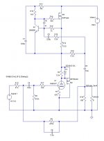
This sounds interesting, to be sure I understand I've posted a schematic. I happen to have a spice model for a Tetrode, figured it's pretty close. I didn't use a CCS in place of R3 but I understand the benefit.
Attachments
Last edited:
Looks right. I would suggest using a lower capacitance Mosfet for at least M1. The Fairchild FQP.... series are good.
Don
I'd agree but at ~30W dissipation one probably wants the lower Rt(jc+cs) of the
TO-247 package. Parallel TO-220s might do the job though... It's mostly Crss
being driven, right? So it's 140pF using the 9240.
Michael
Member
Joined 2009
Paid Member
Eli, that's good to know, I assumed tubes worked at a couple of mA - there's a whole new universe for me to explore if I start learning about tubes. After my degree I did some research with ionized gasses in glass vacuum chambers, space charge regions etc. so all these years later I am about to re-discover a new fascination for me here.
Smoking Amp - I like the tetrode idea, not sure if anybody makes tetrodes, but I guess a pentode is close enough. Still, the suggestion of 'tube rolling' with triodes is perhaps even more interesting. I could give it a try with a 2A3 for instance as I've heard they are particularly 'musical'.
Don't know how I missed that gate stopper
Michael, I'm comfortable with TO-220's from the TGM project, but that only put an idle current of 60mA through them.
I'm not sure how to choose a FET, my experience so far is only with BJTs. I realize that a low gate capacitance is going to help my high frequency performance and reduce the loading on the tube needed to drive it.
Overall, I'm taking it from you guys that the design isn't too far off the right track. I expected it would need more work. Maybe I'll embarass myself by putting together a schematic for the power supply next.
In the meantime I'm afraid I may disappoint you with some slow progress - I still want to build an all BJT version to gain some experience with Class A using low voltages and I guess this isn't the right Forum to track that so I'll have to hop back to SS and work on refining the tube-FET design in parallel.
The friend who has offered me a Triode to use has a bunch he got from Russia - I understand this bodes well ? He also lent me a Canadian made Continental 6AX4 as a teaser to sit on my desk - ever heard of this one ?
"not sure if anybody makes tetrodes, but I guess a pentode is close enough"
Yes, pentode is what I meant. Don't bother with tetrodes, scarce and RF oriented.
The tube rollers are generally using triodes, but pentodes acting as triodes in this fashion have yet to be "discovered". They will have interesting nuances too. Just pick a tube base/socket config. that has a bunch of compatible but varied tubes that fit it.
Don
Member
Joined 2009
Paid Member

- Status
- This old topic is closed. If you want to reopen this topic, contact a moderator using the "Report Post" button.
- Home
- Amplifiers
- Tubes / Valves
- SET amp using Triode-FET complementary feedback pair ?