Member
Joined 2009
Paid Member
Does this have potential ?
I have been looking at how to take full advantage of the linearity inherent in the CFP output stage. The problem is, CFPs are thirsty for current because they hate to switch. The methods I've explored to date for achieving non-switching behaviour have not been that simple or as effective, see: http://www.diyaudio.com/forums/showthread.php?t=146015&highlight=harry77&page=5
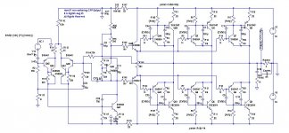
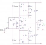
So now I have a design that appears in sims to create a non-switching CFP output which is cleaner although it's rather crude. In the CFP structure the master device is configured as an emitter follower on the output. The slave device wraps around it, taking it's base input from the collector of the master device which is held off the power rail via a resistor (setting the current level in the master device). The signal at the base of the slave is inverted with respect to the output. By providing a level of ac-only negative feedback from the output to the base of the slave device it's possible to keep the slave device always fwd biassed. The current through the output slave device never drops below the idle current which is set by the Vbe multiplier.
I have compared this with a version of the amplifier that uses only EF outputs operating in ClassAB with everything else being equal. The idle current through the CFP stage is set a bit higher, as they are always happier that way but never high enough to operate in full ClassA at the signal levels I'm using.
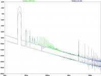
The negative feedback from the output to the base of the slave output devices is accomplished by a resistor & capacitor in series. See attached schematic. Also attached is an FFT plot at 10kHz at two different signal levels of +/-9V and +/-28V output (into 8 Ohms). The green trace (with more spikes) is the standard EF output structure and the blue trace (predominantly H2/3) is the non-switching CFP. It seems to function just as well at higher and lower frequencies; it's particularly clean at lower fundamentals.
How would you refine this ?
I have been looking at how to take full advantage of the linearity inherent in the CFP output stage. The problem is, CFPs are thirsty for current because they hate to switch. The methods I've explored to date for achieving non-switching behaviour have not been that simple or as effective, see: http://www.diyaudio.com/forums/showthread.php?t=146015&highlight=harry77&page=5
So now I have a design that appears in sims to create a non-switching CFP output which is cleaner although it's rather crude. In the CFP structure the master device is configured as an emitter follower on the output. The slave device wraps around it, taking it's base input from the collector of the master device which is held off the power rail via a resistor (setting the current level in the master device). The signal at the base of the slave is inverted with respect to the output. By providing a level of ac-only negative feedback from the output to the base of the slave device it's possible to keep the slave device always fwd biassed. The current through the output slave device never drops below the idle current which is set by the Vbe multiplier.
I have compared this with a version of the amplifier that uses only EF outputs operating in ClassAB with everything else being equal. The idle current through the CFP stage is set a bit higher, as they are always happier that way but never high enough to operate in full ClassA at the signal levels I'm using.
The negative feedback from the output to the base of the slave output devices is accomplished by a resistor & capacitor in series. See attached schematic. Also attached is an FFT plot at 10kHz at two different signal levels of +/-9V and +/-28V output (into 8 Ohms). The green trace (with more spikes) is the standard EF output structure and the blue trace (predominantly H2/3) is the non-switching CFP. It seems to function just as well at higher and lower frequencies; it's particularly clean at lower fundamentals.
How would you refine this ?
Attachments
Last edited:
Gareth,
you steadily keep searching for the truth (there`s nothing wrong with that). You could also take a look at the structure of The Ultimate Suplifier (bridged output, no global feedback). Or just at this great sounding topology with switching output (lateral MOSFET required).
you steadily keep searching for the truth (there`s nothing wrong with that). You could also take a look at the structure of The Ultimate Suplifier (bridged output, no global feedback). Or just at this great sounding topology with switching output (lateral MOSFET required).
Attachments
Member
Joined 2009
Paid Member
you steadily keep searching for the truth
Well as they say "the truth is out there" and this appears to be part of the reason this hobby becomes an obsession

I think for the most part, I already realized that TGM2 amplifier offers sufficient performance in every respect and that I don't need anything else for my listening pleasure for quite a long time. The most limiting part of my system is the quality of the material I'm playing (Chesky CDs being significantly better than anything else in my collection for example).
Still, I am drawn into this hobby like a moth to the flame....
Strange isn't it, the schematic is just a human convenience but during the design phase it makes a big difference to how I feel about the design if the schematic is simple. And it doesn't show the psu or all the work that has to go into the chasis.
I am also, currently somewhat fixated on the (simulated) harmonic spectra as a key indicator, for good or bad. I don't like what I see from switching outputs (yes this is in conflict with being very happy with TGM2). With ClassD you have a big filter afterwards. With Class AB there is no filter afterwards. With Class A there is no switching. I'm drawn to non-switching outputs. Even with some H2/3 it doesn't take much to produce higher order harmonics from IM.
I like CFPs.
Where's the truth for you Lumba ?
Member
Joined 2009
Paid Member
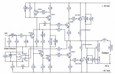
Perhaps the circuit I posted looked a little complex, but we can strip away quite a bit for a simple 50W+ amplifier.
top image - schematic
middle image - current flow through output devices - always non-zero
lower image - FFT (blue) of CFP output verses EF output (green)
top image - schematic
middle image - current flow through output devices - always non-zero
lower image - FFT (blue) of CFP output verses EF output (green)
Attachments
Member
Joined 2009
Paid Member
Some time we really will have some things to talk about. This circuit for one, as I have done some work along these lines.
Well, you can't leave it dangling there like that now can you - I think you'd better spill the beans (email me if it's commercially sensitive)
Gareth,
maybe the truth is written in the stars...but there´s is not only one truth I`m afraid.
I will try to give a more detailed answer successively.
Cris,
darian,
Let me say like this:
The single-ended input gives the sound a nice character.
Possible improvements:
Converting to folded cascode (omitting Q4).
Separate power supply, lowering the output section rail voltage, increasing the bias current to 250- 500mA for a friendly crossover distortion.
A better CFP driver stage.
A more linear input stage:
maybe the truth is written in the stars...but there´s is not only one truth I`m afraid.
I will try to give a more detailed answer successively.
Cris,
In a nasty manner if bipolar. Gareth is right.CFP stages will happily switch on and off.
darian,
Let me say like this:
The single-ended input gives the sound a nice character.
Possible improvements:
Converting to folded cascode (omitting Q4).
Separate power supply, lowering the output section rail voltage, increasing the bias current to 250- 500mA for a friendly crossover distortion.
A better CFP driver stage.
A more linear input stage:
Attachments
Hi Bigun,
I never tease about anything that is commercially sensitive. I don't even mention anything like that. NDAs and all that, and I like to stay out of trouble.
No, more like sitting down with you with some paper, just bouncing ideas back and forth. No way am I going to assume a higher level of knowledge, that's just rude!
Hi Lumba,
Good suggestions as always.
I'm not sure that I agree that CFP in A-B or just B is a bad thing. I can think of so many other unhappy output configurations that are much worse off. I have seen many implementations that are left in class A, so I assume there may have been problems with switch off. Still, that does not condemn every design to poor performance.
-Chris
Edit:
Lumba, is that current source at about 100 mA or so enough to deal with gate charge, or is it not such a problem with those mosfets? I see you are using a CFP input single, cascoded to directly drive the driver transistors. I'm still more comfortable with the extra linearity a diff pair brings to the table. You can still drive the drivers the same way except that we are now talking about a split supply. Any reason why you went with a single supply and output capacitor?
Last edited:
Member
Joined 2009
Paid Member
Gareth,This has a lot of potential.
Excellent, that's what I was hoping for, a vote of confidence
I'd welcome further thought and comments.
Member
Joined 2009
Paid Member
Are the 2n5550's really able to handle the drive for the 2SA1943?
These high power bipolars usually require a driver with a higher power rating than the 650mW rating of this TO92 device.
It was a lazy simulation - I simply don't have the spice models loaded up for the BD139's that actually I use in my TGM builds. Quite right - we need something that can handle the heat.
Anatech,
I have only looked at the CFP output structure in sims but there are clearly issues with switching. The problem is the slave device. When it switches off, there's often a current swing at the base which is felt by the master driving device. I've never seen a good simulated result with CFPs switching off.
Doug Self I believe has some things to say about this - his concern is that the CFP precludes the use of a base charge-suckout capacitor on the slave device. There are some workarounds for this however but I've not studied them.
As a result, CFP is best used in the driver stage for an output where it can be allowed to operate in pure Class A. It is thirsty though, likes a good current flow.
...The future is Class D ?
no, the future is Class A, always was. Now just have to dress up ClassAB so it looks like Class A and we're home...
Hi Bigun,
I always try to keep an open mind. There have been successful amplifiers I have worked on over the years and these were not biased anywhere near class A.
Also, the E-B resistor across the slave transistor can be a low value. Low enough to provide a good discharge path to shut the transistor off. I think you would definitely run into trouble using a higher value resistor in class A-B. I believe that Marantz used a CFP output in the 2245 and other sets of the same era. The E-B resistor in those was 100 ohms. Somehow I can't see a company like Marantz manufacturing a product that had serious design issues.
I am hoping to see another Marantz 2245 in to play with. Our family used to own one and it sounded fine.
-Chris
Hi Chris,
yes, it is a saturation cut-off issue due to charge carrier concentration, an unpleasant crossover distortion and cross-conduction as a result, which has forced some people to go back to EF. The only cure is class A operation, since a fast discharge mechanism, and a large base current supplied by a fast master device are required. The unipolar FETs do not suffer from this. The CFP is a most conducive compound when implemented appropriately and purely. Instability is another problem.
First of all, that in post #9 is a design of Renardson, a respected guy. I`m sorry to say that balanced topologies do not offer the favorable harmonic spectrum of single-ended topologies, although the measured distortion is lower. (Linearity is a mysterious phenomenon). It would have been easy for him to use a long-tail pair to balance the output DC off-set.
Of course, 100mA would be a generous amount of current to handle the input capacitances, in actual fact, it is not much more than 10mA.
Sebastien,
This technique was used by Arthur Bailey and Sugden in their sixties amp which used a CFP output stage. Very clever, I thought.
However, Bigun's idea of a resistor and cap in series loading the collector of the master back to its emitter has lots of merit too.....
Hugh
This technique was used by Arthur Bailey and Sugden in their sixties amp which used a CFP output stage. Very clever, I thought.
However, Bigun's idea of a resistor and cap in series loading the collector of the master back to its emitter has lots of merit too.....
Hugh
Here's something I successfully experimented, providing symmetrical paths for the output devices gate currents. Works fine, however I concluded it's not worth the complexity, and generally CFP output stages are not worth the trouble.
The attached schematic should be considered as conceptual only.
The attached schematic should be considered as conceptual only.
Attachments
- Status
- This old topic is closed. If you want to reopen this topic, contact a moderator using the "Report Post" button.
- Home
- Amplifiers
- Solid State
- non-switching CFP output ?