Hi,
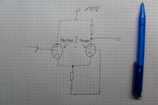
I have a bunch of PCF801 (combined pentode/triode w. common cathode) lying around and would like to build my first tube preamp with them.
Thought about a buffer+grounded grid circuit with heavy negative feedback.
Should I use the triode connected pentode as buffer or the triode?
The frame grid triode may be less affected by low anode voltages, so it may better be used as the grounded grid part.
I want as much open loop gain and less open loop distortion as possible.
Any suggestions?
AND would it work at all?
simplified schematic attached....
Attachments
You could get some inspiration here:
http://webpages.charter.net/dawill/tmoranwms/Elec_Compound2.html
http://webpages.charter.net/dawill/tmoranwms/Elec_Compound2.html
PCF801 line stage on Thai website: why does it not work?
Hallo folks,
Like the previous writers in this thread I would like to build something with the TV tubes which are present in large quantities in my junkbox. Searching for PCF801 applications in audio, I found the attached schematic on a Thai website. I have built a prototype but found out that it does not work! (there is no audio at the output). Yet, the voltages and currents for the triode and pentode sections of the tube are quite OK (they are as indicated in the schematic). Can any of you comment on this finding? I wonder whether there could be any mistake in the schematic. Should the 47 uF cap which has been drawn from anode to ground in real life be connected from the B+ rail to ground?
NB it is of course possible that I made a mistake in the input/output connections, I will still check this.
Thanks in advance for any wisdom you may have,
Aren van Waarde
(aka arensattic)
Attachments
Circuit as drawn is OK
Hallo DF96,
You are right, there was indeed a broken wire in the output cable! After this was repaired I could perform some listening tests. Tested with a portable CD player as signal source and my old and trusty signal tracer as amplifier, the sound of the circuit appears quite OK (good reproduction of the human voice, no hum, no noise, no microphony). But I have not yet looked at the output on a scope (hopefully there are no RF oscillations). Anyhow, the circuit as drawn seems a good start for further experiments.
I have collected several RIAA phono preamp, line level preamp and power amp circuit ideas using P-type tubes, thus after further experiments I may continue this thread. It will perhaps finally result in a completely (Tele)visionary audio system!
Best regards,
Aren
would it work for something like this???
The "$250" Amp? - 6LU8 Compactron SE, UL | Audiokarma Home Audio Stereo Discussion Forums
The "$250" Amp? - 6LU8 Compactron SE, UL | Audiokarma Home Audio Stereo Discussion Forums
Hallo djn,
Your question is not quite clear. If you mean to ask whether a PCF801 can replace a 6LU8, the answer is: "No", since a 6LU8 contains a power pentode with a 14 W anode dissipation rating. The PCF801 is only suitable for preamplifier applications, and even here its use is limited by the fact that its triode and pentode sections share a common cathode.
Aren
Follow up on PCF801 preamp circuit
Hallo folks,
Trouble in paradise: although the audio signal from the PCF801 preamp shown in one of my previous posts sounds mostly OK (using a signal tracer as speaker amplifier), the preamp produces a distorted signal in loud transients. When I examined the output of the gain stage on an oscilloscope, the scope revealed the presence of a very strong RF oscillation in the shortwave region of the spectrum (frequency a few MHz). Caps from the signal grids to ground did not cure the problem. May the current sink with the two 2N2222 transistors be oscillating? Hope anyone can give sound (sic!) advice. Input and output are on opposite sides of the PCB (far apart), thus this seems not to be the cause for unwanted coupling.
Aren
Are the 1k grid stoppers right at the grid pin tags? They should be.
Are the input and output wires from the valve routed in opposite directions? As they carry signals in phase it would take very little stray capacitive coupling to create enough feedback for HF oscillation.
The CCS tail may be oscillating too. Try adding low value base stoppers.
Are the input and output wires from the valve routed in opposite directions? As they carry signals in phase it would take very little stray capacitive coupling to create enough feedback for HF oscillation.
The CCS tail may be oscillating too. Try adding low value base stoppers.
PCF801 problem seems solved
Hallo folks (particularly DF96),
Thanks very much for your helpful suggestions, which I discovered just now. I was trying another potential solution in my attic, viz. soldering a small capacitor (47..100 pF) between the anodes of triode and pentode (tried a small Philips polypropylene). This cured the problem immediately, output looks OK now on the scope. Gain of the circuit is less than promised (between 3 and 4 rather than 5) but for a line stage, this is of course OK. I may experiment further with some of the approaches which you suggested. NB my input and output wires are shielded and far apart, thus this was not the cause of the instability problem.
It always warms my heart when there is a solution for a nasty problem!
Best regards,
Aren
- Status
- This old topic is closed. If you want to reopen this topic, contact a moderator using the "Report Post" button.
- Home
- Amplifiers
- Tubes / Valves
- PCF801 Suggestions