Hi all,
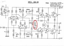
Anybody have experience on DIY Krell KSA 100, please help me for a little. I just wanna know what is the reasonable value of the resistor in the cross distortion in attached schematic.
(which is circled in red): 475 ohm, 4K7 or 4,7M ohm
Thanks in advance,
Chinh.
Anybody have experience on DIY Krell KSA 100, please help me for a little. I just wanna know what is the reasonable value of the resistor in the cross distortion in attached schematic.
(which is circled in red): 475 ohm, 4K7 or 4,7M ohm
Thanks in advance,
Chinh.
Attachments

Well, maybe not at Ratshack but you can get 475 ohm resistors fairly easily. Digikey and similar distributors sell them.JOE DIRT® said:470 ohms would be a safe bet....475 ohms is not a standard resistor
JOE DIRT® said:470 ohms would be a safe bet....475 ohms is not a standard resistor
Doesn't get more standard than that...
However it seems funny to open a thread asking about a resistor that is clearly printed in the diagram...
UrSv said:
Doesn't get more standard than that...
However it seems funny to open a thread asking about a resistor that is clearly printed in the diagram...
Who cares
At least this way we get to see the "secret" Krell schematics... Pretty average looking if you ask me. by the way Blueman, if you have more Krell schematics, please feel free to post!

-K
Based on the schematic. looks like 3 pairs of outputs. If it runs 100watts class-A into 8 ohms, i'd say the bias is as follows:
Total bias 2.5 amp per rail.
Bias per device 0.84 (x3 devices for each cycle of push pull) .
voltage across each emmitter resistor = 416.6mv.
This amp will dissipate 235 watts per channel at idle.
All this is based on the 100 watt class-A spec and the values on the schematic.
Chocoholic and Millwood, did I make you proud?
K-Amps
millwood said:the emitter resistor for the VAS stage (121ohm) is pretty big, considering that JC2 has a 20ohm or so resistor there.
And the current in the VAS is 8,3 ma...
Re: The unbiased vue...
I think it is to reduce degeneration for a/c signals without causing excessive d/c offset. with the cap, the two 200r resistors are essentially tied together, thus no more emitter degeneration.
for a/c signal, the cap is open, thus each leg has a 200r resistor.
Tube_Dude said:The unbiased electolitc capacitor in the emmiters of the LTP...is a strange feature...
Any comments??
I think it is to reduce degeneration for a/c signals without causing excessive d/c offset. with the cap, the two 200r resistors are essentially tied together, thus no more emitter degeneration.
for a/c signal, the cap is open, thus each leg has a 200r resistor.
Tube_Dude said:
And the current in the VAS is 8,3 ma...
if this circuitry behaves like our simulation, the vas is likely running in the 1ma range.
maybe someone will have a service manual for the amp.
K-amps said:Based on the schematic. looks like 3 pairs of outputs. If it runs 100watts class-A into 8 ohms, i'd say the bias is as follows:
Total bias 2.5 amp per rail.
Bias per device 0.84 (x3 devices for each cycle of push pull) .
voltage across each emmitter resistor = 416.6mv.
This amp will dissipate 235 watts per channel at idle.
All this is based on the 100 watt class-A spec and the values on the schematic.
Chocoholic and Millwood, did I make you proud?
K-Amps
With regards to the 3 pairs of outputs I think it could easily be 4 pairs as the schematic clearly says x4 for the output transistors.
millwood said:
if this circuitry behaves like our simulation, the vas is likely running in the 1ma range.
maybe someone will have a service manual for the amp.
Not needed the service manual...if the simulation gives you 1mA...your simulation is flawed...
The current un the VAS is +-8,3 mA...
PS : How a 1 mA current can drive a follower that is not even a triple follower but only a double!???

Re: Re: The unbiased vue...
Yes!
No..i think that what you mean is....for DC !!!
millwood said:
I think it is to reduce degeneration for a/c signals without causing excessive d/c offset. with the cap, the two 200r resistors are essentially tied together, thus no more emitter degeneration.
Yes!
for a/c signal, the cap is open, thus each leg has a 200r resistor.
No..i think that what you mean is....for DC !!!
Tube_Dude said:
Not needed the service manual...if the simulation gives you 1mA...your simulation is flawed...
The current un the VAS is +-8,3 mA...
I thought it was settled on that other thread that for such a topology, you cannot calculate VAS and LTP current. Assuming that the current in the LTP legs is evenly split is falwed.
hopefully, the time and effort there were not wasted.
- Status
- This old topic is closed. If you want to reopen this topic, contact a moderator using the "Report Post" button.
- Home
- Amplifiers
- Solid State
- Krell KSA 100 schematic, resistor value question