I'm reposting this thread as the temporary upgrade forum is now gone.
Anyway this is a D-class amplifier built around the TAS5630 chip from TI.Unlike most bigger D-class chips it dose not need external power transistors or any special drive circuitry. The chip takes a differential or single ended analog input signal and directly drives a speaker on the other side.This makes it very easy to build a powerful D-class using it.(Its almost as simple as a AB-class chip amp) The chip has internal feedback in order to achieve very low distortion.Not many people know about this great chip as it was just released recently
Now the 300W in BTL si a little overrated from TIs side as that is already a bit in to clipping.The chip actually stays below 1% THD up to 240W and most of the range stays well under 0,1%
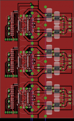
The PCB is only 100x160 mm and thats pretty small for the kind of power thing thing is capable of.To distribute the power to the amps i plan on a thick bus bar running down the PCB (Shown in blue) As i think that is the best way to provide a very solid connection to the power and ground for all amps.The board is also has a separate analog ground that is loosely connected to power ground.As for the 7 pin headers they carry the differential audio signal and two control lines since its going to be MCU controlled (reset for the amp and a ready signal to confirm the amp is working)
I never relay plan to use this amp to the max,main ting is to have lots of headroom and to keep the chips nice and cold without a massive heat sink.
Oh and someone asked about kits of it. Well i never made a kit before but if this was a kit it would also have to be optionally preambled because the chips are 0,65mm pitch SMDs and most audio hobbyists only worked with trough hole stuff.
TAS5630 Datasheet: http://focus.ti.com/lit/ds/symlink/tas5630.pdf
Anyway this is a D-class amplifier built around the TAS5630 chip from TI.Unlike most bigger D-class chips it dose not need external power transistors or any special drive circuitry. The chip takes a differential or single ended analog input signal and directly drives a speaker on the other side.This makes it very easy to build a powerful D-class using it.(Its almost as simple as a AB-class chip amp) The chip has internal feedback in order to achieve very low distortion.Not many people know about this great chip as it was just released recently
Now the 300W in BTL si a little overrated from TIs side as that is already a bit in to clipping.The chip actually stays below 1% THD up to 240W and most of the range stays well under 0,1%
The PCB is only 100x160 mm and thats pretty small for the kind of power thing thing is capable of.To distribute the power to the amps i plan on a thick bus bar running down the PCB (Shown in blue) As i think that is the best way to provide a very solid connection to the power and ground for all amps.The board is also has a separate analog ground that is loosely connected to power ground.As for the 7 pin headers they carry the differential audio signal and two control lines since its going to be MCU controlled (reset for the amp and a ready signal to confirm the amp is working)
I never relay plan to use this amp to the max,main ting is to have lots of headroom and to keep the chips nice and cold without a massive heat sink.
Oh and someone asked about kits of it. Well i never made a kit before but if this was a kit it would also have to be optionally preambled because the chips are 0,65mm pitch SMDs and most audio hobbyists only worked with trough hole stuff.
TAS5630 Datasheet: http://focus.ti.com/lit/ds/symlink/tas5630.pdf
Attachments
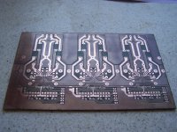
The board dimensions are 10x16cm thats i think thats 4x6,4 inches.
Heatsink is simply to be bolted to the boards coper side with screws so it presses against the chips.
Powersupply for the logic is 12V while the supply to the output stage is 20-50V. It can be switching or the regular transformer.
Heatsink is simply to be bolted to the boards coper side with screws so it presses against the chips.
Powersupply for the logic is 12V while the supply to the output stage is 20-50V. It can be switching or the regular transformer.
")
Well i dont relay know what thickens it is but it seams to be a pretty thick material to me. There are lines on the board to fill with solder too so it improves conductivity.
Right now my focus is on the DSP that i have a thread on the digital forum. So progress might be a little shower but working on it
Right now my focus is on the DSP that i have a thread on the digital forum. So progress might be a little shower but working on it
- Status
- This old topic is closed. If you want to reopen this topic, contact a moderator using the "Report Post" button.
- Home
- Amplifiers
- Class D
- Tiny 6x300W amp(repost)