Dear fellow DIYers;
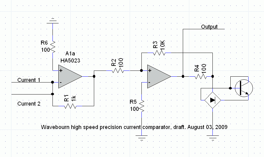
I am looking for a fast and precision current comparator, to compare currents +/-20mA, up to 1 MHz. What I am thinking about, to use a video opamp in inverting connection, then another one with open loop. However it will work, but may be you can suggest some better solutions?
I will share results of the project with the DIY community, when good high-end results will be obtained.
Anatoliy
jcx said:if you want digital output then you really should look at monolithic comparators which handle overdrive and have hysterisis to prevent oscillations - which are problems with op amps optimized for closed loop operation and continuous analog signal
I can add hysteresis in opamp, no problem. Do you mean oscillations through power supply, or through parasitic capacitances?
Which monolithic comparators would you recommend?
Bi-polar output will be more convenient in my application, however it is not absolutely necessary.
Wavebourn said:What are weak points of such a solution?
20 mA input currents that I compare is not necessary, I mean, enough of current to deal with parasitic capacitances.

If I correctly understand your schematic, the main (not the only) weak pont is that the A1a HA5023 under certain condition (ie Current 1=20mA, Current 2=0mA) saturates suffering for delay to recover from saturation.
There is a paper from Robert Pease about the use of an OpAMP as precison voltage comparator
http://europe.elecdesign.com/Articles/ArticleID/9973/9973.html
Two questions:
1) If I understand your goal your circuit doesn't compare if Current 1 > Current 2 but if Current 1 > - (Current 2).
Is it correct?
2) Which is the purpose of the bridge + diode connected transistor on the second OpAmp output?
1. Who is Blomley?
2. As I said, it is just an idea. However, no way I can allow the video opamp to saturate. Couple of fast diodes on input, for example, would prevent this, but I prefer linear input resistance close to zero, so feedback resistor would be smaller, let it be 240 Ohm (for 20 mA+20 mA = 40 MA, +/1 8.6V out).
3. The purpose of a bridge and a Zener is to stabilize threshold of hysteresis. However, it should be more sensitive, say R3 = 1 mOhm, need to be calculated against capacitances.
PMA said:Blomley is Peter Blomley.
Thanks; but how he is related to my current comparator? Excuse me for my ignorance.
PMA said:
Ah no, it is not about phase splitting. It is about a fast precision current comparator. It compares 2 symmetrically swinging currents with frequencies up to 1 MHz and values up to 20 mA and shows fast and precise differential between them as an infinitely amplified voltage.
darkfenriz said:How about a current conveyour?
What is it?
seriously current conveyor is a similar concept to operational amplifier, but it has two low impedance inputs and a high impedance output, nomen omen.
It has a intrisic speed, because there is no voltage gain inside.
Your patterns may work, but every transimpedance stage made around a resistor in negative feedback loop may have problems with stability.
It's because from 'voltage' point of view, input impedance is infinite, and resistance in feedbackloop is given, so the 'voltage' gain is below 1, which is something most opamps hate.
darkfenriz,
Excuse me, but you probably meant to say "no current gain".It has a intrisic speed, because there is no voltage gain inside.
- Status
- This old topic is closed. If you want to reopen this topic, contact a moderator using the "Report Post" button.
- Home
- Amplifiers
- Solid State
- Fast and precision current comparator


