Hi all, I got some 1J6G dhts but can't find anything but class B typical operation specs. Does anyone who's used them have any suggestions?
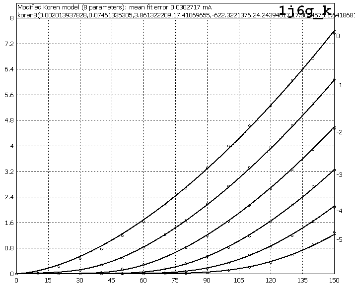
I managed to measure the current and then draw the curves using curvecaptor.
I'm thinking of 4.9mA, Vg=-1V, Vp=135V. I'm sure someone uses these tubes, please advise.
I managed to measure the current and then draw the curves using curvecaptor.
I'm thinking of 4.9mA, Vg=-1V, Vp=135V. I'm sure someone uses these tubes, please advise.
This might be of interest:
http://www.diyaudio.com/forums/attachment.php?s=&postid=1745232&stamp=1234649115
Provenance: http://www.diyaudio.com/forums/showthread.php?s=&threadid=138356&perpage=25&highlight=&pagenumber=4
Simon
http://www.diyaudio.com/forums/attachment.php?s=&postid=1745232&stamp=1234649115
Provenance: http://www.diyaudio.com/forums/showthread.php?s=&threadid=138356&perpage=25&highlight=&pagenumber=4
Simon
Hi.
Just looking at your plate curves 4.9ma at 135v would leave very little room to swing any voltage and would likely exceed maximum plate power dissipation as well.
Try drawing a line from 135 volts to about 4 or maybe 5.6 ma.
This defines your load resistor R=E/I. Grid bias somewhere between -1 and -2.5 volts depending on if you want lowest distortion or highest gain/headroom.
Cheers.
From the data sheet it's not clear what the max plate voltage or current should be. The swing at the plate should be around 8-9V, for the headphone amp I'm planning to build. Also, I'd like to keep the input p-p signal to about 500mV.
Since this is a double triode, I've also measured the two halves paralleled. Here's what it looks like, if anyone may need it for simulation or design. For the two in parallel maybe 3mA at 140V. Since I'm planning to use either a ccs load or a gyrator load, it's not exactly like drawing a resistor load line, or am I wrong here?
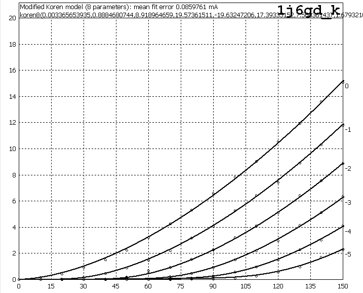
Since this is a double triode, I've also measured the two halves paralleled. Here's what it looks like, if anyone may need it for simulation or design. For the two in parallel maybe 3mA at 140V. Since I'm planning to use either a ccs load or a gyrator load, it's not exactly like drawing a resistor load line, or am I wrong here?
The swing at the plate should be around 8-9V, for the headphone amp I'm planning to build. Also, I'd like to keep the input p-p signal to about 500mV.
I guess for what you are doing that would make sense.
but....
From the data sheet it's not clear what the max plate voltage or current should be.
I would suspect that with the operating point near the upper right hand part of the curves, the tube may be running too hot.
Since I'm planning to use either a ccs load or a gyrator load, it's not exactly like drawing a resistor load line, or am I wrong here?
Don't know what a gyrator is but with a ccs, loadline is horizontal at your chosen current.
Cheers.
rman said:I guess for what you are doing that would make sense. but.... I would suspect that with the operating point near the upper right hand part of the curves, the tube may be running too hot. Don't know what a gyrator is but with a ccs, loadline is horizontal at your chosen current.
Cheers.
I'm just a beginner. There's a nice discussion about a gyrator in this thread. A solid state choke.
As for the tube running hot, yes, it's very probable. That's the reason I was looking for someone who may be using or may have been playing with this tube. I know some tubes can be pushed a little (e.g. type 46).
BTW, this is where I may be using the 1j6g.
I'm just a beginner too.
It seems you know a fair bit about how to use solid state parts and about some fairly complex circuits.
I have always had an interest and some knowledge, but only really got into electronics when I built my first amp about three years ago.
I have concentrated on tube basics.
Thanks for the link, I'll try to figure out how a gyrator does it's thing for curiosity.
Hope your headphone amp turns out great.
- Status
- This old topic is closed. If you want to reopen this topic, contact a moderator using the "Report Post" button.
- Home
- Amplifiers
- Tubes / Valves
- 1J6G recommended operating point?