I have a lm3886 amplifier, which is based on the application note. The amplifier has given me a hard time to operate correctly, first i had an uncurable hum. Which I thought was a ground loop but was caused by the trafo.
Now i have some sort of very slow oscillation. I already have a sollution but frankly I don't completely understand how my own sollution works") . So I will give a try to explain my cure and hope somebody can explain why this problem arises in the first place.
. So I will give a try to explain my cure and hope somebody can explain why this problem arises in the first place.
The amp is being fed through an elco bank (30.000uF) and then on the pcb by a small cap (1000uF) near the chip. If the main elco bank is connected directly to the pcb, my speakers reveal a very slow oscillation. If I connect my scope, the oscillation is gone. So at first I thought i had some sort of earthing oscillation thing going on. But then I thought I could also have some sort of oscillation between the cap bank and the 1000uF cap on the pcb, so I decided to try damp it by inserting a 1 Ohm resistor in between them and it appears that the oscillation is gone.
But now the explanation??? Can this behaviour be attributed to an oscillation between to a cap bank and a local cap and if so what would exactly happen. And what is the role of the scope, at first I thought it was the high input impedance, which stops the oscillation but only leaving the earthing connector in place seems to be sufficient (the amp is not connected to safety earth, should it be?).
What makes it hard to figure this thing out is that as soon as I connect a scope all things wierd things dissappear. So I have to figure this thing out in my head, which is hardly functioning anymore after a long debugging session.
In my frustration I also blew up a gainclone by mistakenly connection the +Vcc to the minus and vice versa, so I cannot reproduce if the gainclone 'suffers' from the same effects. (and also cannot check the difference in sound between both amps and the effects of a big cap bank on the sound )
)
I hope somebody can shine some light on my rainy day
Now i have some sort of very slow oscillation. I already have a sollution but frankly I don't completely understand how my own sollution works
. So I will give a try to explain my cure and hope somebody can explain why this problem arises in the first place.The amp is being fed through an elco bank (30.000uF) and then on the pcb by a small cap (1000uF) near the chip. If the main elco bank is connected directly to the pcb, my speakers reveal a very slow oscillation. If I connect my scope, the oscillation is gone. So at first I thought i had some sort of earthing oscillation thing going on. But then I thought I could also have some sort of oscillation between the cap bank and the 1000uF cap on the pcb, so I decided to try damp it by inserting a 1 Ohm resistor in between them and it appears that the oscillation is gone.
But now the explanation??? Can this behaviour be attributed to an oscillation between to a cap bank and a local cap and if so what would exactly happen. And what is the role of the scope, at first I thought it was the high input impedance, which stops the oscillation but only leaving the earthing connector in place seems to be sufficient (the amp is not connected to safety earth, should it be?).
What makes it hard to figure this thing out is that as soon as I connect a scope all things wierd things dissappear. So I have to figure this thing out in my head, which is hardly functioning anymore after a long debugging session
. In my frustration I also blew up a gainclone by mistakenly connection the +Vcc to the minus and vice versa, so I cannot reproduce if the gainclone 'suffers' from the same effects. (and also cannot check the difference in sound between both amps and the effects of a big cap bank on the sound
)I hope somebody can shine some light on my rainy day
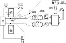
The schematic is based on the one on page 1 of the lm3886 pdf, with the difference that the input is not constituted by a pot and a 1k, but instead the signal passes through a 1k res then a 2u2 cap and then through a node where one arm goes to the +In and the other arm goes trhough a 47k resistor to the ground. So nothing fancy. For the power supply a 25V trafo is used, then a double bridge configuration going to the previously describe cap bank and the cap on the pcb.
The oscillation is gone if the scope is connected to the amp ground.
What I mean by slow oscillation is that if the 'damping resistors' between the cap bank and the local cap near the chip is not present I see the conus of the speaker moving rather slowly back and forth, it takes a couple of seconds for a complete cycle. And the amplitude is increasing continously, I don't think the speaker is enjoying this low level large amplitude movement a lot......
From what do you want to see a picture? The slow oscillation is only visible on the speaker and that would take a movie to see it.... It cannot be seen on the scope.
Emiel
edm said:and the other arm goes trhough a 47k resistor to the ground. So nothing fancy. For the power supply a 25V trafo is used, then a double bridge configuration going to the previously describe cap bank and the cap on the pcb.
The oscillation is gone if the scope is connected to the amp ground.
From what do you want to see a picture? The slow oscillation is only visible on the speaker and that would take a movie to see it.... It cannot be seen on the scope.
Emiel
Hi,
did you try usual input circutry? With same results?
Are on your trafo 2 secondaries or one?
This oscillation is very dangerous for speaker, replace with some resistor when testing.
Regards
It indeed sounds like you have grounding problems and perhaps the 'oscillation' is motor boating .... what does it sound like? I doubt that this problem will be particularly harmful to your speakers as it seems from what you are discribing, the problem is in the bass region not the treble where destructive oscillation often occurs ... It may be best to test on a $5 full range driver until the problem is rectified.
EDIT: Just reread the above posts. It sounds as though the ground reference of the chip is shifting relative to the power ground that the speaker is connected to. Where is the -ve of the speaker connected to in your circuit? Best keep your good speakers disconnected for the time being.
EDIT: Just reread the above posts. It sounds as though the ground reference of the chip is shifting relative to the power ground that the speaker is connected to. Where is the -ve of the speaker connected to in your circuit? Best keep your good speakers disconnected for the time being.
I do not understand what you mean, could you please refrase?moamps said:
did you try usual input circutry? With same results?
2 secondaries, which are connected to two bridges and from those bridges two are paired and connected to ground.moamps said:
Are on your trafo 2 secondaries or one?
I have tried to connect the -ve of the speaker to the central star ground and to the local ground on the pcb, both with identical results.AudioFreak said:EDIT: Just reread the above posts. It sounds as though the ground reference of the chip is shifting relative to the power ground that the speaker is connected to. Where is the -ve of the speaker connected to in your circuit?
Although I would rather like to keep them disconnected the only way I could see the instability is to keep the speakers connected... Because connecting the scope across the speaker posts 'solves' the problem....AudioFreak said:Best keep your good speakers disconnected for the time being.
But why is the subsonic oscillation gone after the insertion of a 1.2 ohm resistor between the main cap bank and the local cap bank????
Before i started i never would have thought that wiring everything together would be the difficult part...... But Murphy likes playing games with me....
edm said:Although I would rather like to keep them disconnected the only way I could see the instability is to keep the speakers connected... Because connecting the scope across the speaker posts 'solves' the problem....
That's exactly why I suggested that you get a cheap full range driver for testing purposes.

edm said:
I do not understand what you mean, could you please refrase?
Hi,
did you try with 1K and pot (or trimmer for test purpose) on +input?
Regards
Nope I will try to do so tomorrow...moamps said:
Hi,
did you try with 1K and pot (or trimmer for test purpose) on +input?
Regards
same outletpinkmouse said:Where is your 'scope grounded? is it the same outlet or a different one?
Currently everything is placed in large wood box, which is there to prevent my cats from being electrocuted (they have some fetish for wires)pinkmouse said:Is your chassis grounded?
[/B]
I have tried to attach safety earth to the star point and the earths of the preamp and amp are connected through a 100 Ohm resistor bypassed by a 100nF cap (have also tried without in all possible permutations).pinkmouse said:Is your amp circuitry grounded to the chassis?
[/B]
For what exactly should I be looking?pinkmouse said:If so, have you checked the ground in your lead/supply/socket? [/B]
I also found out that on the amp side at the input I have some noise, which is not there on the preamp side. If the preamp is disconnected the noise worsens. Could this also be related to the grounding scheme?
edm said:
What I mean by slow oscillation is that ... I see the conus of the speaker moving rather slowly back and forth, it takes a couple of seconds for a complete cycle.
I had this happen once when I was running an amp from a bench supply and had the current limit set too low.

Does that give you any ideas?
2 suggestions
This is only a shot in the dark:
A- It's thermal. The chip heats up, which for some unknown reason gain and current draw fall off until it cools off. The chip is supossed to have thermal protection but I didn't think it worked like this - just off-on-off-on.
B- 30KuF seems like a lot for a stereo pair. Maybe the chip doesn't draw enough to keeps the caps charged, especially if the bleed resistor is to low a value.
Both sound hairbrained to me - B worse than A, but it's all that I can think of that might cause a SLOOOOW oscilation.
Audiofreak,
I already tried that no oscillations... I need some stimilus of some sort (noise for that matter) in order to get the slow oscillation going on (without the damping resistors). So what is your hunch what is causing this
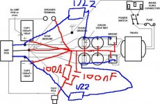
Moamps, this is my grounding scheme (fear my paint skills )
)
The red lines are the ground lines, mostly consting of 2.5mm^2 massive copper wires using in between the elcos as a star ground point. The blue lines the power supply lines and I also sketched the 'damping resistor'.
Oh and I don't have a 100nF near the elco's yet nor the 22k 2w (bleeder??) resistor. I think i will put a 100nF near the elco's (but first i need to etch/solder some pcbs for a passive filter for a friend of mine)
emiel
I already tried that no oscillations... I need some stimilus of some sort (noise for that matter) in order to get the slow oscillation going on (without the damping resistors). So what is your hunch what is causing this
Moamps, this is my grounding scheme (fear my paint skills
)The red lines are the ground lines, mostly consting of 2.5mm^2 massive copper wires using in between the elcos as a star ground point. The blue lines the power supply lines and I also sketched the 'damping resistor'.
Oh and I don't have a 100nF near the elco's yet nor the 22k 2w (bleeder??) resistor. I think i will put a 100nF near the elco's (but first i need to etch/solder some pcbs for a passive filter for a friend of mine)
emiel
Attachments
I'd say that the input ground reference is shifting relative to the power ground reference. Because your amp is not referenced to earth, the absolute DC values are shifting around the place relative to the source which I suspect has it's ground tied to earth. If you connect the safety earth to the ground point of your circuit it will almost certainly fix your problem.
Well there is only one way to find out, i'll remove the damping resistors attach the safety ground to the star ground and see what happens... I left the safety ground floating to get rid of the motorboating, but with the introduction of the 100Ohm bypassed with the 100nF i hope i can attach it again..
I'll post the results, when i'm done etching.
I'll post the results, when i'm done etching.
As an alternative to attaching earth to the circuit ground. You could do the following:
1) Leave the source ground disconnected from the amp so that the interconnect is only connected to ground at the source and use the amplifiers ground point for the amp.
2) AC couple the input to the amp
This should prove equally effective at fixing your problem and is probably less likely to cause motorboating. Of course, you also need to consider the safety aspect if you plan to leave the earth pin disconnected.
Hi, edm
I think that your ground scheme is slightly incorect. IMHO
Please read my posts on http://www.diyaudio.com/forums/show...3858&perpage=15&highlight=moamps&pagenumber=2
Regards
I think that your ground scheme is slightly incorect. IMHO
Please read my posts on http://www.diyaudio.com/forums/show...3858&perpage=15&highlight=moamps&pagenumber=2
Regards
- Status
- This old topic is closed. If you want to reopen this topic, contact a moderator using the "Report Post" button.
- Home
- Amplifiers
- Chip Amps
- Weird slow oscillation