Hi 
I am working on a 3 Transistor hifi headphone amplifier.
1. Input uses N-JFET, like 2N4416 or 2N3819, which is more easily found.
2. One bipolar PNP turns the signal to correct phase
and drives the output stage.
3. Output IRF610 N-Channel MOSFET follower powers the load resistor into several 100mA Class A.
Be back with schematics, AC-analyses and Fourier for discussion/evaluation.
All is properly tested in virtual circuit with some of the best instruments we can find.
On the commercial ground my simulator costs way too much.
---
From this we can forsee, that this topic will not discuss my circuit.
But people will do more postings of the usual debate on using sims, paper or calculator
or design by listening to transistors output through headphones of different qualities
after throwing it quickly together with solder.
And hope you have a lucky day and that your luck will stay with you
as you change this and that capacitor or resistor.
So just another good amplifier idea is completely ruined by these off topic posters.
Those that are not really interested in design,
but only to show how clever they are and how good diyaudio builders
and how golden their audiophile ears are.
Those they were born with and have finetuned to perfection in many a sessions with a bunch of them other audio-jet-setters.
lineup
I wont change the basic concept = 3T
Neither I want any changes to my original idea
like fooking CCS ideas.
If you want to make your own ravishing unique amplifier
start your own topic and start worrying about problems in that circuit
But suggestions regarding what transistors are very welcome.
In such very basic and simple designs
we can not just throw in non-fitting devices
and think any 'tons' of feedback will cover up for a bad design idea.
/lineup
--
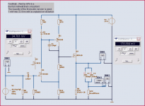
Attached is the first public version.
Running @ the important first milli watt level, 1 mWatt into speaker.
Of course by trial and error there were version before this one.
They simple were nothing much to publish and get my well deserved critic for.
From all you fooking knowledege besserwissers out there
Attachments
I am beginning to think we could become good friends
- if ever we meet.
One good friend, not fiend, is enough to miss my dead mother less.
(passed away in a heavy brain stroke at 29 October,
I carried her wooden box to the hole my self on Friday 28 Nov 2008)
Any good man reading a lineup post is worth notice.
Any good man posting a comment, Nelson or Scott, is remembered for ever .. I have a daarn good memory for things!
Dont you mistake me for old and hard-to-remember syndrome
eventhough i just at the 22nd of May
celebrated my 2-years-before-60 birthday totally alone in my 1-room-flat
without a bdaycake or even one candle to light up my day.
You want proof I am not just talking, but I'm alive and living, too?
Here you are (in perfect destroyer X - Carlos M. fashion).
There is always one in a crowd.
One that does not give a daaaamn about not wearing a yellow jacket.
Perhaps he doesnt even have the money to buy suitable dull black tuxedo ..
And he is not very much afraid of crying out loud his tears
.. if and when they want to come down his cheeks
Attachments

Scott Wurcer suggestion J305 input
I have, as John Curl usually like to put it (and from a scientific point of view this makes good sense)
maintained 'all things else equal'.
Which means
~1mA input (the default J305 is a 6mA IDDS)
~20mA in second BD140 stage to drive the input capacitance of MOSFET
~360mA in output IRF610
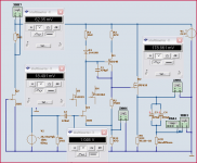
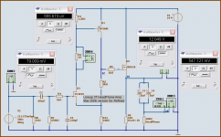
This below is the resulting circuit for Scott Wurcer suggestion to try
= one J305 N-Fet for input.
difference in gain is now almost x10
vs. ~ x5 in Lineup original PN4416A (almost equivalent to 2N4416 JFET)
In next post I will show the compare of Fourier analysis
at output level of First Milliwatt = 1 mW into 32 Headphone (fully resistive!)
I have, as John Curl usually like to put it (and from a scientific point of view this makes good sense)
maintained 'all things else equal'.
Which means
~1mA input (the default J305 is a 6mA IDDS)
~20mA in second BD140 stage to drive the input capacitance of MOSFET
~360mA in output IRF610
This below is the resulting circuit for Scott Wurcer suggestion to try
= one J305 N-Fet for input.
difference in gain is now almost x10
vs. ~ x5 in Lineup original PN4416A (almost equivalent to 2N4416 JFET)
In next post I will show the compare of Fourier analysis
at output level of First Milliwatt = 1 mW into 32 Headphone (fully resistive!)
Attachments
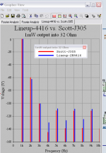
The fourier show almost the same.
Only fractionally higher distortion in Scotts circuit,
with a lower level of even order harmonics especially 4th, 6th, 8th etc.
Conclusion:
If we want to have, need as high voltage gain as x10 ( +20dB)
then go for J305 as Scott suggests.
This can be most suitable for HP:s with an impdance at 300-600 Ohms.
Like the very good best ones by Sennheiser.
Among world's finest, but very expensive, HeadPhones.
Otherwise, you get a more decent gain of x5 with 2N4416
as suggested by Lineup.
This is suitable for lower impedance HP:s like 32-100 Ohm.
Think for example Grado classics series of HiFi phones.
/lineup, circuit design - May 27th 2009
Attachments
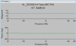
This is a rather interesting analysis.
I think my few readers, pupils if you like, will agree totally
AC Analys = Frequncy response + Phase behavior within the audioband.
We are most interested, of course, how one machine that is involved with sounds behave vs. audiable signals.
In this case via one pair of Headphones.
More specifically we are concerned with what we can hear.
We leave other things to the bats and the supersticious
Usually most music takes place between 50 - 10.000 Hz for a normal middleage white man.
Black women, according to tests, has got a slightly better hearing = larger spectrum they can hear.
John Curl, syn08 and older white skinned men like Scott and me
.. we just have to be happy with what we still can perceive.
Inside the audioband, we strive for a stright line, 'stright wire' behavior.
The ideal Amplifier is said to be like a very short wire
Well, friends ---
... using 2N3819 (25VDS) + BC560C(45VCE) for 2nd stage, I think we have come very close.
At least me my self. Maybe later you. too
Comments are welcome.
This one uses 0.5mA in JFET and
~ 5mA in the PNP BC560C low noise high gain device.
Attachments
lineup said:I am beginning to think we could become good friends
- if ever we meet.
lineup - Don't take such a simple component substitution so seriously. A lot of FET's would work in that position, just plug them in and see what you get no big deal.
You have yellow jackets and I had one of my father's best friends come to his wake after a whole liter of vodka so we suffer our friends because there is no other way.
Wavebourn said:What if to remove that Miller cap, but to add a gate stopper?
scott wurcer said:lineup - Don't take such a simple component substitution so seriously. A lot of FET's would work in that position, just plug them in and see what you get no big deal.
You have yellow jackets and I had one of my father's best friends come to his wake after a whole liter of vodka so we suffer our friends because there is no other way.
You are right Wavebourn .. there is not even a need for one miller in that stage.
It was removed before I read your post.
I added a simple R C to the gate of input JFET, with a small pF to GND from gate.
This plus one gate stopper R to IRF610 follower, rolls off nicely at Overall 800 khz at gain 5.x for 2N3819 input circuit.
I doubled the output C. Paralelled two 1.000uF -> for 32 Ohm only.
For 300 Ohms HP we can use 1/10 ~ 220uF higher quality caps,
if somebody is are afraid good standard electrolyts wont do a good job.
Note:
all my testings and curver and fourier is taken after the output caps.
That is across the load.
Probably a slightly too ideal capacitance.
Real capacitors might be foumnd in Sim Library, but at least I did pick from Electrolyts = polarized caps.
PN4416A is only 15 V.
They are good FETS, but as you say Scott, there are a big number of different that will work in that position.
I prefer to look for those giving a VGS around 2 Volts at 0.5 - 2.0 mA.
Any more nice ones suggestions are most welcome.
Because 16Volt/2V gives ~ gain x5 ... set by the 2 resistors in 2nd stage.
There are not as many of those JFET (VGS 2V at 1-2 mA)
and some can be hard-to-find-for-normal-people-in southafrica and Maylasia .. not to mention Monglia Western part.
Like Nelson Pass, I try to use mainstream stuff: .. this is why IRF610 easy-to-find.
N-JFET 2N3819 is a good DiyAudio companion. Think used in Radio-circuits.
BC560C for second stage .. wouldnt give any headache for any DiyAudio member that is used to discrete constructions.
I will keep this topic alive .. on the hitlist.
Will post my latest diagram, which made that nice and straight
AC-Analysis
- wasnt that very interesting curves to contamplate???
lineup said:Nobody has noticed the strange diode ...
This was what would raise a lot of debate 1N4148.
You might think the designer, Lineup, made a mistake.
Because what does this diode do to the first and second stage ?????
Nobody noticed something that resembles a current mirror in my headphone amp you were writing about recently?
Are you kidding Lineup?
My MOSFET issue
Hi
Lineup here again!
I have tried all I can to optimise first and second transistor.
I got a working JFET (2N3819) and one low noise cheap BC560C.
But I reached a limit.
Where it does not matter what I do .. there are only fractional improvements to make, with the chosen devices.
So I begin to look at the remaining weak point. What has not been worked on:
- The Ouput follower = MOSFET IRF610 (This is of typr HEXFET and one TO-220 in this case)
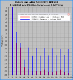
The issue with MOSFET is that it is put outside the Feedback loop.
Below you have the before and after.
This harmonics analys speaks for itself.
This time it is one Sennheiser 300 Ohm being the load.
But there is almost no difference in quality across any load.
32 Ohm or 300 Ohm gives only minute small difference in Fourier.
This comes from 2 things:
1. The current is so high in output ~360 mA
and the load is working parallell into the 33 Ohms resistor, that loads the MOSFET.
2. No matter what we do .. the IRF610 will create the dominating distortion.
The 2 input transistors are almost uneffected by the load.
This diagram, Fourier, speaks for itself.
Some would call this MOSFET output a problem.
I would not.
Let me stay by name it 'One Issue'
IRF610 contributes not only higher 2nd + 3rd,
but also a heeellllof higher order ODD harmonics distortion.
/lineup
Hi
Lineup here again!
I have tried all I can to optimise first and second transistor.
I got a working JFET (2N3819) and one low noise cheap BC560C.
But I reached a limit.
Where it does not matter what I do .. there are only fractional improvements to make, with the chosen devices.
So I begin to look at the remaining weak point. What has not been worked on:
- The Ouput follower = MOSFET IRF610 (This is of typr HEXFET and one TO-220 in this case)
The issue with MOSFET is that it is put outside the Feedback loop.
Below you have the before and after.
This harmonics analys speaks for itself.
This time it is one Sennheiser 300 Ohm being the load.
But there is almost no difference in quality across any load.
32 Ohm or 300 Ohm gives only minute small difference in Fourier.
This comes from 2 things:
1. The current is so high in output ~360 mA
and the load is working parallell into the 33 Ohms resistor, that loads the MOSFET.
2. No matter what we do .. the IRF610 will create the dominating distortion.
The 2 input transistors are almost uneffected by the load.
This diagram, Fourier, speaks for itself.
Some would call this MOSFET output a problem.
I would not.
Let me stay by name it 'One Issue'
IRF610 contributes not only higher 2nd + 3rd,
but also a heeellllof higher order ODD harmonics distortion.
/lineup
Attachments
Re: My MOSFET issue
Hi Lineup
good that somebody else is not afraid of N-GNFB projects,
yes, 610 in this case generates "lots" of high order harmonics, but they are bellow -100dB! They are masked by 2 and 3rdh!
I could bet that its sound is better than any high loop gnfb amp!
I could even resign in a local feedback in VAS section...
lineup said:IRF610 contributes not only higher 2nd + 3rd,
but also a heeellllof higher order ODD harmonics distortion.
/lineup
Hi Lineup
good that somebody else is not afraid of N-GNFB projects,
yes, 610 in this case generates "lots" of high order harmonics, but they are bellow -100dB! They are masked by 2 and 3rdh!
I could bet that its sound is better than any high loop gnfb amp!
I could even resign in a local feedback in VAS section...
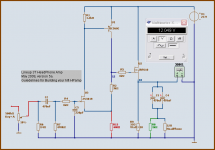
Music in HeadPhones Lovers!
I post the latest version 5a
This was the version used in diagram of 'Before & After' MOS testing.
You can see the circuit nodes numbered '12' and '10'.
Normally I use the amp output node '16' .. for my posted testings.
To find these 3T transistors would not be a problem.
- IRF610 is frequently used in Nelson Pass preamps and amplifiers
- BC560C is one standard Low Noise 'audio' transistor. Very much bangs for few bucks
- 2N3819 the input JFET can be found in most electronics shops
I just pulled away the diode 1N4148 from my first schematic.
Likewise now I use the full gain of BC560C (DC gain like 400-600!!)
This is utilized by removing the resistor between U1 Emitter and V+ rail.
Enjoy:Attachments
Hello musik lovers!
Some guidelines for the actual build.
---------
1. Red wires to and from potentiometer should be fair quality shielded cable.
2. Potentiometer value is not critical. Log 100k - 500kohm will work
3. Instead of pot you could use a resistor divider e.g. 100k-10k. Adjust to suit your sound source output
4. Red resistor 440 ohm sets the output to Close 12 Volt (50% of V+24V)
Temporarily you can use one 1k trimpot to find out what you need.
Start at setting the trimmer at 50% and work from there.
This is an asjustament done to suit for your 2N3819.
JFETs have a bit different parameters for each and every single Transistor we buy
5. Output cap(s) is your own choice. Depends on impedance of you phones.
For 32 Ohm you could use two 470uF - 1.000uF .. or one
For 300 Ohm impedance Sennheiser you can use two 100uF .. or one
6. R8, green resistor, is to help charge Output electrolytic caps
With two 470uF and R8=1kohm we get like 1 second to charge
if there is no headphones attached.
7. Please note! The R9 power resistor should be rated >=10Watt
You can use four 33 Ohm rated 2.5W - 5 Watt parallelled in a square.
Code:
 |  |
33 33
 |  |
33 33
 |  |
Of course, me and other DiyAudio guys will answer any questions
and guide you perfectly on your way towards a very well sounding amplifer.
No matter what headphones you use.
The sound can, will be a nice surprise to any taking my design seriously.
Ask Wavebourn!
He is using same type of circuit idea in his headphone amplifiers ...
/Lineup - your audio friend - full copyright reserved, though!!!
Attachments
- Status
- This old topic is closed. If you want to reopen this topic, contact a moderator using the "Report Post" button.
- Home
- Amplifiers
- Solid State
- 3T HeadPh Amp. JFET-BJT-MOSFET