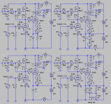
Below are four of many possible solutions of DC-coupling a driver to an output tube in a SE-poweramp.
The anode is DC-connected to the grid of the presceding stage.
To keep bias potential OK (no need to bother about tube-aging) a CVS(gyrator) is used instead of a CCS.
But are they really DC-connected") ? One must take a close look at the PSU´s to determine.
? One must take a close look at the PSU´s to determine.
What do you think?
The anode is DC-connected to the grid of the presceding stage.
To keep bias potential OK (no need to bother about tube-aging) a CVS(gyrator) is used instead of a CCS.
But are they really DC-connected
? One must take a close look at the PSU´s to determine.What do you think?
Attachments
Hey Shoog,
Check again, there is only waste in ONE of the circuits .
The others are a smart way to get rid of the input transformer you use, by just moving the ground connection.
But the question isn´t about waste, it is about if DC-connections really are DC, as the other pole through the PSU must be taken in account.
Check again, there is only waste in ONE of the circuits
.The others are a smart way to get rid of the input transformer you use, by just moving the ground connection.
But the question isn´t about waste, it is about if DC-connections really are DC, as the other pole through the PSU must be taken in account.
I see what you mean - clever work. Still needs two power supplies which is a bit of a pain.
I am not really qualified to answer your question, but I think they are DC coupled because the two +B in your circuit are effectively at AC ground.
One observation I would make is that those CCS can take a brutal burst of voltage on switch on and many are not up to the job. I had to use the IXY 900V chips in my Tabor clone.
Shoog
One observation I would make is that those CCS can take a brutal burst of voltage on switch on and many are not up to the job.
Sorry my mistake, there should be a RC link added from B+ to CVS. In this particular case the CVS only needs to be fed by 250-300V. DN2540 is what I stock and they can take 400V.
OldEurope has an interesting circuit for DC coupling.
http://coupling-triode.blogspot.com/
OldEurope's circuits surprise me from time to time.. this is one of
them.
http://coupling-triode.blogspot.com/
OldEurope's circuits surprise me from time to time.. this is one of
them.
OldEurope has an interesting circuit for DC coupling.
Hi Jueic,
Sorry, that one had nothing to do with the subject. It is still about the PSU pole, not the DC-coupling between tubes.
Hi, Revintage
Are we reading the same thing ?? or my english reading is out of wack ?
By looking at T3, the input feeds thru PLATE, and the output taken from CATHODE.. the coupling tube works as a diode which
has an adjustable plate voltage set by cathode resistor (sort of auto-bias).
Maybe you are right, the OldEurope's circuit adds one more tube stage in-between..it is not pure DC-coupled. but it does not need
the coupling cap we normally have.
To me, it is really an interesting circuit.
Hi,
OK, get your point. Still it is not about what I want to discuss here.
My question and idea is that there seldom are such things as DC-coupling as the pole through the PSU in fact mostly is cap-coupled. In other words we are fooling ourselves!
One have to use a cap-free, lowZ series- or shunt-regulated PSU to achieve this.
OK, get your point. Still it is not about what I want to discuss here
.My question and idea is that there seldom are such things as DC-coupling as the pole through the PSU in fact mostly is cap-coupled. In other words we are fooling ourselves
! One have to use a cap-free, lowZ series- or shunt-regulated PSU to achieve this.
revintage said:Hey MJK,
Want your comment on this as it concerns the same topology we are both building
First I needed to realize that the current loop of your driver supply
goes through the B+ supply ;-) But that pole is isolated by MOSFET.
There is indeed at least a low frequency pole in almost everything that
isn't regulated. Two of your topologies use a regulated driver supply.
and would appear to be mostly DC stable.
Isn't there also a time constant involved in the gate coupling C and
the 1Meg DC reference? If the driver waveform is asymmetric there
will be a small DC shift + time constant with signal level. Keeping the
driver in the symmetric range and small R should mitigate this though.
I think there is a big difference in terms of which current loop the
time constant is in. I would expect more audible artifacts in the
cathode branch vs. the anode branch, the common regulated driver
but unregulated B+ in DC topologies may bear this out.
And what is the goal in direct coupling? For me first and foremost
is to eliminate blocking distortion, where even minute grid current
causes the coupling cap to charge and discharge on peaks. I find
this pretty annoying, and DC is one solution.
Second order is the ability of the output stage to maintain a stable
operating point as signal level changes. This is a side effect of fixed
bias, not DC. Single supply circuits for example have a problem
here, where the big cathode R allows the cathode voltage to
increase at high signal level. Choice of a flat load line can mitigate
this to some extent. A shunt regulator can also be used instead of
a resistor in the cathode branch to simulate fixed-bias using a single
supply.
Third is the ability to drive class A2 with these circuits. Referencing
a separate grid drive supply to the cathode keeps the grid current
in a small local loop for cleaner class A2 operation (stay tuned...)
How do you see the difference between series and shunt driver
regulators? The series one using PMOS followers is adaptable to
cathode feedback, which I also want to try with these transmiting
tubes as a way to deal with the high Ri.
One reason for me to use input transformers is that I'm powering
my breadboard with bench supplies that have a 250V max DC
offset and I need a lottle more for the driver. I also have all Low Z
balanced sources (Alesis Masterlink and mixing consoles) so
the transformers are pretty much transparent.
For a real build, I would probably go with stacked/floating supplies
and shunt regulation of the driver, or waste the power and try a
shunt cathode regulator with the single supply. Or the series
follower if I wanted to try cathode feedback.
Michael
Greetings from Tacoma.
My apologies, revintage for taking things even farther away from your area of interest. I spent last night reading about a related project and I suggest the following: Bobs Hi-Fi Tube Amp Page . If that link doesn't work I will find you another route. You are asking a heavy question here.
My interest in DC coupling is that the cathode follower (ex 12AX7 with 100K plate resistor and 33 - 47K cathode resistor) has always had the reputation for "warming" up a guitar amp. Same for triode SE output. Well, I built my 2A3 amp and cathode followers in the preamps, and I can't hear the difference. I decided that my next project should be to put several cathode followers in series. I have no training in electronics, but it seems logical that 1) all of the followers would need to round up the same half of the wave, so there will have to be 180+180 degrees of phase inversion between each cathode follower and 2) there can be no phase shift from a poor choice of blocking cap/grid resistor. So, jueic's post is interesting to me. Since no one out there is trying to make a guitar amp with lots of 2nd order harmonics there isn't much to look at on the web. If either of you can get me past the grid bias problem for what is coming out of the cathode follower and going into my inverter, I would appreciate it. I don't care if I need to make a bipolar power supply, I just want to hear those second order harmonics before I die.
Thanks
Hoagje1
What you're describing isn't a cathode follower. A CF has the plate at AC ground (usually connected to B+) and takes the signal from the cathode. Gain is less than unity and there's no polarity inversion.
For high 2nd harmonics, just run a normal common cathode stage with a small plate resistor. For example, using a 30k plate resistor in a 12AX7 stage will give you lower gain (maybe 30) and very high second harmonic.
For high 2nd harmonics, just run a normal common cathode stage with a small plate resistor. For example, using a 30k plate resistor in a 12AX7 stage will give you lower gain (maybe 30) and very high second harmonic.
As far as I see it, the signal out from the driver stage is ground referenced. Hence, the ground connection must be DC coupled as well as the signal connection. As far as I can see, only the top two circuits accomplish this.
I'm mucking with a similar circuit: http://www.diyaudio.com/forums/tube...300b-idea-request-comments-3.html#post2440807
~Tom
I'm mucking with a similar circuit: http://www.diyaudio.com/forums/tube...300b-idea-request-comments-3.html#post2440807
~Tom
- Status
- This old topic is closed. If you want to reopen this topic, contact a moderator using the "Report Post" button.
- Home
- Amplifiers
- Tubes / Valves
- DC-coupling of tube stages