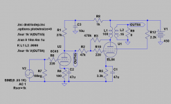
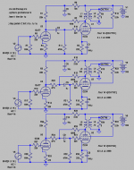
Instead of foolishly using the triode drivers Ri for feedback(high driver THD), this must be a better way to do it. Used ca 10% local NFB as proposed by Schade. Surely the circuit can be fine-tuned. I get indications of below 1% THD both in the driver and total circuit at 4W/8ohm.
Attachments
I am impressed Motorola used 6C45") ! So you probably didn´t look close enough!
! So you probably didn´t look close enough!
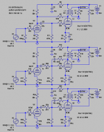
The interesting thing is that when you go from circuit 1 to 2, distortion is cut almost in half when the local NFB ala Schade is adjusted to give the same total gain as in circuit 1.
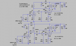
Forgot to add the simplified circuit from post #3:
! So you probably didn´t look close enough!The interesting thing is that when you go from circuit 1 to 2, distortion is cut almost in half when the local NFB ala Schade is adjusted to give the same total gain as in circuit 1.
Forgot to add the simplified circuit from post #3:
Attachments
Hi Douglas,
Mentioned the Ri in post #1.
Maybe you missed the point. Distortion is halved from 1 to 2.
The method used in 1 only works with pentodes.
Look at the point where the feedback resistor returns to the EL84 grid. If we had infinite gain from the pentode this would be a virtual earth point. Due to finite gain we just have a very low impedance. A triode driver will have gross problems.
With a shunt/Schade inverse-feedback as in 2 and 3 we a have a definded input impedance of in, this case, ca 47k. Now we can find a triode driver that works OK!
An interesting variation of the shunt feedback Lars.
Inserting a serias resistor before the EL84 will make the load on the driver more "benign". The voltage swing required will however increase by a factor of about 4 due to the voltage divider represented by the 47K and Rfb (Rfb being in effect about 470K/33).
So it seems that whatever way we do it, there is a very delicate balance between feedback ratio, gain, and distortion.
What do you recon is the ovarall gain of the modified topology, and what would be the (simulated) output impedance?
Atached loadlines is my rough estimate of the two variants using 12AT7/ECC81.
Svein
Attachments
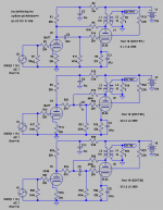
I prefer to call it "Schade" as this variation of shunt feedback around a output tetrode was proposed by him.
I choose the shunt feedback to give exactly the same total gain and output impedance is on par. THD is halfed in the Schade.
The variation recommended by you and others, is IMHO no good enough and with about double the THD compared to the Schade. A triode driver does not work so good under those circumstances.
Started the thread as I couldn´t see the benefit of the earlier variation when using triode drivers.
Could just put a Mosfet follower between the triode plate and the output pentode's grid to unload the triode.
Another idea that comes to mind is to use a non-linear (diode like) feedback resistor to match the driver triode's non-linear Rp. Like the Aikido input stage, using a triode or diode load on top of the driver, and anti-bootstrap the load top from the output tube plate. Diode/triode load would need an Rp of 100X or so of the triode driver Rp to get 10% NFDBK (output stage gain factor * Rp_driver/Rp_Load).
Or keep the triode driver current constant using something like this:
http://www.diyaudio.com/forums/showthread.php?postid=1775419#post1775419
Lots of video tubes with a triode and pentode in a single bottle.
Don
Hi Don,
Your solutions are always so radical ! Have to put on the big thinking-cap to even understand half of them . Will check into them later.
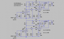
Tried this one a while ago and it will only work with circuit 2 as circuit 1 uses the driver-triodes Ri as feedback-resistor. It lowers THD a bit due to less load on the driver. Check attachment below. feedback adjusted for same gain. THD is 1/3 with 12AT7 at 1W. With 6C45 it is 1/5!
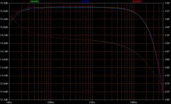
About circuit 1 of the three, I just made a sim to find out Zin of the EL84 with the 100k feedback resistor. No wonder this creature kills the 12AT7. As suspected Zin is very low and seems to be in the ballpark of 2k! So the poor 12AT7, that in itself is less than linear, will have to deliver ca 5V into 1,75k//22k~1,5k for max output power.
Circuit 2 has the disadvantage, as mentioned by Svein, of having a lower sensitivety than circuit 1, but now Zin is 47k. Must be easier for any driver to deliver 20V into 47k//22k~15k.
When feeding the two circuits with another generator, Ri=10k, sensitivity is 25V for circuit 1 and 35V for circuit 2.
Using the Ua/Ia-diagram of 12AT7 at 157V/5,84mA to calculate 2nd order distortion also shows high distortion for circuit 1 at ca 8%. Using circuit 2 gives below 3%. These figures are for a bypassed cathode. I am not exactly sure how it will look with an unbypassed cathode as in the actual circuit, but the higher Zout from the driver will not make things better, even if the local NFB compensates ,I guess.
I might have misunderstood the whole concept but to me plate-to-plate-feedback with an unlinear triode-driver seems to be a total disaster.
Your solutions are always so radical
! Have to put on the big thinking-cap to even understand half of them. Will check into them later.Could just put a Mosfet follower between the triode plate and the output pentode's grid to unload the triode.
Tried this one a while ago and it will only work with circuit 2 as circuit 1 uses the driver-triodes Ri as feedback-resistor. It lowers THD a bit due to less load on the driver. Check attachment below. feedback adjusted for same gain. THD is 1/3 with 12AT7 at 1W. With 6C45 it is 1/5!
About circuit 1 of the three, I just made a sim to find out Zin of the EL84 with the 100k feedback resistor. No wonder this creature kills the 12AT7. As suspected Zin is very low and seems to be in the ballpark of 2k! So the poor 12AT7, that in itself is less than linear, will have to deliver ca 5V into 1,75k//22k~1,5k for max output power.
Circuit 2 has the disadvantage, as mentioned by Svein, of having a lower sensitivety than circuit 1, but now Zin is 47k. Must be easier for any driver to deliver 20V into 47k//22k~15k.
When feeding the two circuits with another generator, Ri=10k, sensitivity is 25V for circuit 1 and 35V for circuit 2.
Using the Ua/Ia-diagram of 12AT7 at 157V/5,84mA to calculate 2nd order distortion also shows high distortion for circuit 1 at ca 8%. Using circuit 2 gives below 3%. These figures are for a bypassed cathode. I am not exactly sure how it will look with an unbypassed cathode as in the actual circuit, but the higher Zout from the driver will not make things better, even if the local NFB compensates ,I guess.
I might have misunderstood the whole concept but to me plate-to-plate-feedback with an unlinear triode-driver seems to be a total disaster
.Attachments
Now I see what all that $4 gasoline has been paying for. I wonder what the elevator looks like? http://www.cnn.com/2008/WORLD/meast/06/25/duibai.tower/index.html
Smoking Amp (Don),
I actually wanted to reply to the low part of your posts (I do not know what would be the name for it...) -- but never got to it.
Point is, 4.00 USD for gasoline might be a lot now, since it was cheaper previously... but the rest of the world was not subsidised to keep up the "way of life". Therefore, it is not that much.
Furthermore, it does not build Dubai, because oil is much cheaper at the source than 4.00 USD -- and because there is not that much oil in the Emirates. The retail price of gasoline is a different issue and heavily influenced by the government of the country where it is sold. You might as well post a link to some large american car, and say that it is paid (actually, facilitated) by the 4.00 USD (per gallon!) gasoline.
Or, you might show a missile or an aircraft carrier and say that is is paid by the 4.00 USD gasoline.
AND, this is not a political post, unless fighting naivety is a political issue.
Thanks, and regards.
Alex Kitic
physics and limitations
It is an interesting issue when someone invents himself a thread and then keeps posting in the thread hoping that it will grow. The best thing is when the guy says he will ignore my posts... so this probably mean that he will not be aware they exist, or not aware of the content 

Well, the laws of physics cannot be bent. The humble EL84 can produce up to 5W of power, as it has maximum anode dissipation of 12W (in theory, up to 50% with pentodes, but more realistically, some 40% is the maximum achievable in class A from a single tube).
Therefore, no matter what the driver, the power will be limited to the mentioned 4-5W.
There is nothing foolish about using the triode drivers Ri for feedback... but there are people who are foolish enough to boast their ignorance. Actually, maybe a pentode would do better, due to its even higher Ri. Those in the know do understand why
To me, your ambition and drive seem a total disaster
So the poor ReVintage cannot understand why he has to do everything by himself, and how come that people seem to misunderstand him.
To all those interested, there is a point where further amplification of the signal in this series of amps is not possible, actually does not lead to any positive results. The point is clearly visible on the sims I have posted on various threads of this forum, and is represented by the 1kHz waves combined (driver and output tube). To put it plainly, there point where those two waves touch is the "end point". After this there is no point in increasing the signal on the driver tube, because it will only lead to further and fast increasing distortions.
Yes, quite like that. Therefore, if you want to have more power, move to a more powerfult tube. Or, even better, try PP amps... Finally, you can always buy a 150W Krell amp -- it is much simpler than designing your own amp, and you do not need to know any physics or electronics to be able to do it!
It is an interesting issue when someone invents himself a thread and then keeps posting in the thread hoping that it will grow. The best thing is when the guy says he will ignore my posts...
so this probably mean that he will not be aware they exist, or not aware of the content Well, the laws of physics cannot be bent. The humble EL84 can produce up to 5W of power, as it has maximum anode dissipation of 12W (in theory, up to 50% with pentodes, but more realistically, some 40% is the maximum achievable in class A from a single tube).
Therefore, no matter what the driver, the power will be limited to the mentioned 4-5W.
Instead of foolishly using the triode drivers Ri for feedback(high driver THD), this must be a better way to do it.
There is nothing foolish about using the triode drivers Ri for feedback... but there are people who are foolish enough to boast their ignorance. Actually, maybe a pentode would do better, due to its even higher Ri. Those in the know do understand why
I might have misunderstood the whole concept but to me plate-to-plate-feedback with an unlinear triode-driver seems to be a total disaster.
To me, your ambition and drive seem a total disaster
So the poor 12AT7, that in itself is less than linear, will have to deliver ca 5V into 1,75k//22k~1,5k for max output power.
So the poor ReVintage cannot understand why he has to do everything by himself, and how come that people seem to misunderstand him.
To all those interested, there is a point where further amplification of the signal in this series of amps is not possible, actually does not lead to any positive results. The point is clearly visible on the sims I have posted on various threads of this forum, and is represented by the 1kHz waves combined (driver and output tube). To put it plainly, there point where those two waves touch is the "end point". After this there is no point in increasing the signal on the driver tube, because it will only lead to further and fast increasing distortions.
So it seems that whatever way we do it, there is a very delicate balance between feedback ratio, gain, and distortion.
Yes, quite like that. Therefore, if you want to have more power, move to a more powerfult tube. Or, even better, try PP amps... Finally, you can always buy a 150W Krell amp -- it is much simpler than designing your own amp, and you do not need to know any physics or electronics to be able to do it!
High Z drive, low Z drive, some other figure inbetween...
Makes little or no difference. Simple topology tweak can
accommodate either extreme.
What matters here: Driver Z is is resistive and constant.
That the entire Schading network as much as possible
should be resistive and constant. If you really want it to
behave like an intrisic Mu..
Makes little or no difference. Simple topology tweak can
accommodate either extreme.
What matters here: Driver Z is is resistive and constant.
That the entire Schading network as much as possible
should be resistive and constant. If you really want it to
behave like an intrisic Mu..
kenpeter said:
What matters here: Driver Z is is resistive and constant.
That the entire Schading network as much as possible
should be resistive and constant. If you really want it to
behave like an intrisic Mu..
I triode plate is hardly constant...hence my love of pentode, or triode/MOSFET cascode in the simplified version I call E-Linear.
cheers,
Douglas
The Mosfet follower, with the buffered feedback (post 13), should maintain the same EL84 output Z I would think when varying the driver's cathode resistor (but that would change input signal sensitivity of course). So a buffered triode driver stage could be set up with a CCS plate load and whatever cathode resistor is convenient for biasing.
Putting a pentode in for the driver will need sufficient cathode resistance to linearize it's V to I transfer function. So the D3a might need a bit more cathode R and boosted grid bias to perform up to expectations.
"triode/MOSFET cascode "
The cascode setup loads the triode with a dead short unless the top Mosfet has its gate voltage controlled by feedback. Maybe the E linear setup is doing that? Could be done for P-P with crossed feedbacks to the gates, but SE will have a problem with this.
"Your solutions are always so radical ! Have to put on the big thinking-cap to even understand half of them...."
Well, the Aikido input stage manages to heavily load the 1st triode while retaining (theoretically) low distortion. This is fairly apparent that it works in the Aikido case since it just halves (in the typical configuration) the plate resistance of the triode.
What I suggested above is similar in nature. A high Rp diode load for the triode will have the same non-linear V/I curve as the triode plate. (both devices being fairly clean 3/2 power law here since the plate does not suffer island effect like a g1 does) Both devices have the same current thru them (anti-bootstrap from the output back to the top of the diode load) so they track co-non-linearly. The resistance ratio is what counts for setting the feedback, and that is held constant here. Just have to find a diode with about 100X the rp of the triode.
The triode/pentode combined driver scheme just uses the pentode (with degenerated cathode) to remove as much current loading off the triode as possible. The pentode's high Zout avoids interfering with the triode's low Zout Mu processing. Similar to just using several tubes in parallel to reduce loading on each one. Could just use a bunch of the same triode in parallel too. The pentode is simply adjusted in gain to mimic the triodes, and offload the load current. (this only works well for cases with a known and constant load Z)
"Dubai....."
Yes, I'm aware of the details. However the price per barrel did plummet dramatically once the world recession hit. I was just joking about everyone paying through the nose for gasoline while "they" built "pyramids". Sorta like the gasoline station attendents who wore Arab outfits to dispense gasoline until some irate customer shot at them.
Don
Well, the Aikido input stage manages to heavily load the 1st triode while retaining (theoretically) low distortion. This is fairly apparent that it works in the Aikido case since it just halves (in the typical configuration) the plate resistance of the triode.
Wrong! Don´t forget there is no external load on the Aikido-triode as it is feeding a CF. Also the upper RK is unbypassed. A sim of an Aikido with 12AT7 B+=300V Rk=250 reveals that the upper triode loads the lower with in the ballpark of 25k. At 1V in we get an indication of just below 1% THD. Not a heavy load in my eyes!
Compare this to 2k for the initial circuit 1!
- Status
- This old topic is closed. If you want to reopen this topic, contact a moderator using the "Report Post" button.
- Home
- Amplifiers
- Tubes / Valves
- Schade84