Hello everybody !
I have problems with my Aleph 30 starting up because of fuse blowing on +/- 24 V rails. I built testing circuit which consists of power transformer rated at 600 VA with 230 V primary, fuse 2A SB
and thermistor in series. The secondary of the transformer is 4x18V with bridge and capacitance of 20 000 uF per rail. I got +/-24 V after rectyfing and have 5A FB fuse on each rail which blew, within a second or so, after switching on the power supply. I have checked the circuit twice and it seemed to be OK yet I use panos29 PCB layout which was used many times in this forum. The only thing I added to the PCB are Z1-Z4. I reduced the value of R19 to 30k but it brought about no changes.
Transistors used:
IRFP240, IRF9610, ZTX450, R19 - 47k5
I'm thinking about switching to BC550 as a control transistor but I'm not sure wheather I'm right. Please help me !
Thank you in advance.
Regards
Tomek
More informations please
Hi Tomasz,
did you buy the PCB or did you make them yourself ? in this case haven't you invert the side ?
The gate of an IRFP240 is on the left when you have it in front of you(that for R28- R30 and R31- R33), the same for the 9610. I don't think that the other components (z1,Z4) can be the source of your problem.
Give us more informations and I hope we will find the problem.
Yonnat
I'd like to thank everybody fot the suggestions which led me to found the problem, it turned out to be trivial, simply I should have used slow blow fuse at the secondary or not to use them at all.
So I did yesterday and everything seemed to be OK. I will soon post some readings which I got and I will attach some pictures.
Regards
Tomek
So I did yesterday and everything seemed to be OK. I will soon post some readings which I got and I will attach some pictures.
Regards
Tomek
I fired both channels up yesterday and it seemed to be everything OK, although I haven't listened to this amp yet. After two hours of warming up I could easily touch the heatsinks feeling no pain or discomfort. Here are some measurement readings:
Voltage across 3W MF resistors (0,51 ohm, matched)
right channel
R37 - 0,39 V
R38 - 0,39 V
R39 - 0,39 V
I=2,29 A
R34 - 0,41 V
R35 - 0,39 V
R36 - 0,39 V
I=2,32 A
left channel
R37 - 0,42 V
R38 - 0,42 V
R39 - 0,40 V
I=2,44 A
R34 - 0,41 V
R35 - 0,42 V
R36 - 0,41 V
I=2,42 A
I think that currents on each rail seem to be within the limits, but I don't know wheather I should change some of the resistors so as the voltage across each pair is the same or maybe the differences are so small that do not impede future operation. Any suggestions and comments will be really appreciated.
Regards
Tomek
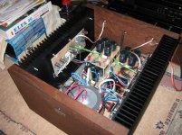
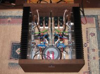
Here is my amp in pieces.
Voltage across 3W MF resistors (0,51 ohm, matched)
right channel
R37 - 0,39 V
R38 - 0,39 V
R39 - 0,39 V
I=2,29 A
R34 - 0,41 V
R35 - 0,39 V
R36 - 0,39 V
I=2,32 A
left channel
R37 - 0,42 V
R38 - 0,42 V
R39 - 0,40 V
I=2,44 A
R34 - 0,41 V
R35 - 0,42 V
R36 - 0,41 V
I=2,42 A
I think that currents on each rail seem to be within the limits, but I don't know wheather I should change some of the resistors so as the voltage across each pair is the same or maybe the differences are so small that do not impede future operation. Any suggestions and comments will be really appreciated.
Regards
Tomek
Here is my amp in pieces.
Attachments
Good Work!
Its probably silly enough,but it feels very nice to see people using my design of aleph pcbs for their beloved machines! Actually I took apart my aleph and cut the heatsinks in half so I could use these vertically as this causes the temperature to go down about 10 degrees celsius, so I am in the processs of heatsinkdrilling and upgrating the resistors and capacitors right now.
About your measurements seem good enough, but you got to measure the dc offset at the output(after warm up with no load). If it is lower than 50-100mv just hook up your speakers and enjoy! If not I would interchange the mosfets between R35 and R39 on your left channel and maybe fine tuning the input differential current source, adjusting R11 from 180-470 Ohms for lower dc offset.
Happy listening!
Panos
Thanks a lot Panos29 for your advices and of course for your design of PCB layout which I used in my project. I'm going to follow your suggestions this weekend then I can find out how good (or how bad) sonically my amp is.
Regards
Tomek
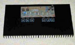
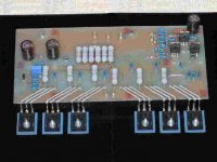
this is complete board for one channel
Regards
Tomek
this is complete board for one channel
Attachments
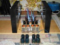
Hello again !!!
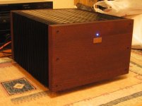
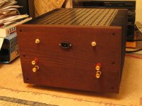
At last !!! May Aleph 30 is completed. I'd like to thank everybody who helped me. It works perfectly with outstanding sound and great depth. I think it also looks very nice. Any questions or suggestions ? Do not hesitate to post a reply or to contacy me.
Of course it is not the end of my Pass adventure so stay tuned for the next part - Bridge of Zen !
Regards
Tomek
These are a few pics of my amp !
Attachments
I can't understand why people insist on using fuses on secondaries. If one of them blows for any reason, your speaker's woofer will be gone too. A fuse on primary is enough protection. A fuse on secondaries creates unnecessary danger. I didn't see them in Aleph schematics.Tomasz Rodak said:simply I should have used slow blow fuse at the secondary or not to use them at all.
Nice job, BTW
Pass DIY Addict
Joined 2000
Paid Member
Peter: the fuses on the secondary probably comes from Randy Sloan's book on high-powered amps. He has a chapter on building power supplies and places one fuse on the primary, and one on each secondary.
I think his rationale is that if the bridge blows, you run the risk of cooking the secondary before the primary fuse blows...
I think his rationale is that if the bridge blows, you run the risk of cooking the secondary before the primary fuse blows...
- Status
- This old topic is closed. If you want to reopen this topic, contact a moderator using the "Report Post" button.
- Home
- Amplifiers
- Pass Labs
- Aleph 30 - fuse blowing