Hi,
This is my CFL inverter and he works fine, except¡K.. (of course nothing work fine without exceptions ƒº) The temperature of the transformer is 75¡¦C. Is that normal? I tried with large wire diameter. Nothing. His dB swing is 400mT (for Bmax= 200mT)
Np = (3.14/2)*(0.707*Vin*3.14)*(20uS /2) / (Ac*dB)
Ac = 0.83cm2
DB = 0.4T
IM I wrong or missing something ?
Attachments
FWIW: I am not a CFL expert. Off the top of my head, I would guess you have a flux walking problem that is leading to saturation. You are using a push-Pull circuit to drive your transformer. If there is small difference in inductance or coupling between the two halfs of the primary it can cause the transformer to walk in one direction leading to saturation. You should be able to determine which half is walking into saturation by comparing the current levels between each half (or perhaps by simply measuring which transistor is hotter).
You can correct this by either adding some deadtime, changing topology (half-bridge or Full-bridge), or using a Push-Pull controller that can correct flux-walking problems.
You can correct this by either adding some deadtime, changing topology (half-bridge or Full-bridge), or using a Push-Pull controller that can correct flux-walking problems.
This is a current fed converter and they normaly do not have flux walking. I wound a quite unbalanced traf - the temp is 75C! I tryed with free runing caps from 150nF to 2nF - same thing. I wound a traf on p36x22 (Ae = 2cm2) with dB = 200mT (Bmax = 0.1T)! Now the temperature is 65C. I thing that this is becouse he have bigger surface!
Hi,
Honestly this is a poor design. You could improve the circuit by adding a controller IC. For the CFL Inverters that I made, I used SG3525 with MOSFETs in push-pull topology(no feedback/voltage regulation needed) switching a ferrite trafo at around 70kHz with the output rectified to DC using ultrafast rectifiers and filter caps and inductors.
Hope this helps.
The reason why the transformer gets hot is the huge flux density. Check the core data sheet - there are graphs that help in defining the core losses at given frequency and flux density. Basically you can reduce the flux by adding more turns, but this brings other concerns.
Then again, if the transformer stays at these temperature levels, I wouldn't worry too much - it is still at relatively safe level. When the core heats up, the loss density within the core reduces - less core losses with the same flux density.
Then again, if the transformer stays at these temperature levels, I wouldn't worry too much - it is still at relatively safe level. When the core heats up, the loss density within the core reduces - less core losses with the same flux density.
The wire is hot, not the core.
I make a couple of another designs.
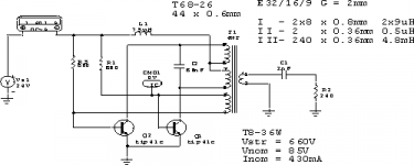
This is a voltage feed case with IR2156 and variations with E25 and E32 cores.
In second case the core temp is less, but the wire is still hot.
Secondary wire dia = 0.36mm
Primary wire dia = 0.6mm
Wound:
First is Secondary in 3 layers, insulation, then Primary in 2 layers.
I make a couple of another designs.
This is a voltage feed case with IR2156 and variations with E25 and E32 cores.
In second case the core temp is less, but the wire is still hot.
Secondary wire dia = 0.36mm
Primary wire dia = 0.6mm
Wound:
First is Secondary in 3 layers, insulation, then Primary in 2 layers.
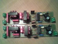
Attachments
Picture on www.efob.hit.bg
It is in bulgarian.
It is in bulgarian.
Attachments
Then you have to choose a wire with greater diameter. Usually a value 3 A / mm^2 is used - but you should still calculate the wire resistance (first calculate the dc resistance, then find out the ac resistance, check wikipedias article on Proximity effect). You should also be aware of the coil current rms values.
Yes, these calculations seem to be ok. Only that commonly the area is denoted with 'A' instead of 'S'. 'S' means Siemens, that is unit of conductance (inverse of resistance, ohm).
It seems that your current will be 0.4 A. Now find out the mean length per turn for your transformer - then you can calculate the dc resistance:
Rdc = (rho*N*MLT)/Ae,
where rho = resistivity of copper (@ 100 degrees celsius), N = number of turns, MLT = mean length per turn, Ae = wire area.
It seems that your current will be 0.4 A. Now find out the mean length per turn for your transformer - then you can calculate the dc resistance:
Rdc = (rho*N*MLT)/Ae,
where rho = resistivity of copper (@ 100 degrees celsius), N = number of turns, MLT = mean length per turn, Ae = wire area.
- Status
- This old topic is closed. If you want to reopen this topic, contact a moderator using the "Report Post" button.
- Home
- Amplifiers
- Power Supplies
- CFL inverter