Depends on price. I guess that the EL84s draw about 40-45mA? The 12AT7 about 5-10?, that would make for about 100mA total. What looks interesting is that the choke is only specified at 50mA for both channels...
If there is a price difference, I would go for a lower spec. 200mA is enough for a stereo PP EL84.
If there is a price difference, I would go for a lower spec. 200mA is enough for a stereo PP EL84.
I've seen V2 G1 conduction at drive levels far less
than required for the full rated output, squashing
and distorting the drive signal to unrecognizable.
Zob and I had to buffer it with a circuit similar in
concept to Tubelab's Superdrive... That fixed it.
Maybe it was his SV83's, not the normal EL84?
I forget if we tried my RCA 6BQ5's in it or not...
here are the two EDCOR that am debating on
120v primary, 300-0-300 @200mA, 6.3v @ 4A, 5v @ 3A cost is $57.33 each
Shipping cost is $11.60 via USPS priority mail flat rate.
120v primary, 275-0-275 @ 175mA, 6.3v @ 4A, 5v @ 3A cost is $51.15 each.
right now my amp is drawing 37ma per el84 i dont know about the 12at7 but im guessing 80ma to 100ma altogether.
Maybe I was thinking of Zob's 12B4A amp? Forget if we applied
the same fix or different with his RH84? Anyways, stOOpid trick
for abusing a CCS to keep the second coupling cap topped off
with +5VDC, regardless how much A2 might flow.
I think he was running screen voltage pretty low (for SV83),
maybe that was why we were havin to drive G1 so hard???
I can't find our schematics relevant to the RH84, but the drive
buffer mod is almost exactly the same, I'm almost sure, aside
from the usual RH84 Plate to Plate feedback thing goin'on...
Attachments
kenpeter said:stOOpid trick
for abusing a CCS to keep the second coupling cap topped off
with +5VDC, regardless how much A2 might flow.
OK, what AUDIBLE effect if any does this trick have?
tim614 said:here are the two EDCOR that am debating on
120v primary, 300-0-300 @200mA, 6.3v @ 4A, 5v @ 3A cost is $57.33 each
Shipping cost is $11.60 via USPS priority mail flat rate.
120v primary, 275-0-275 @ 175mA, 6.3v @ 4A, 5v @ 3A cost is $51.15 each.
right now my amp is drawing 37ma per el84 i dont know about the 12at7 but im guessing 80ma to 100ma altogether.
Damn, I just bought two Hammonds for a pair of monoblocks... Those Edcor prices are good! Get the one with the closest matching voltage spec, the 300-0-300 I think...
Originally posted by korneluk
OK, what AUDIBLE effect if any does this trick have?
Plate to plate feedback don't linearize nothing when drive
bleeds away in G1 conduction. Again, this might not have
been a problem if he used the right pentode (and screen
voltage) to begin with.
Mod finally made amp tolerable to listen to, above ~1W.
Is that what you are asking?
Zobsky said was impossible to make an RH84 sound bad,
but somehow he had managed it... Took a little work with
an oscilloscope to identify the real problem. And it was the
same as we had just seen (and fixed) with his 12b4a.
12AT7 plate has a problem driving a grid that wants to leak.
I don't know why grid was so leaky on his 12b4a. But with
his SV83, I suspect because G2 was kept deliberately low.
We modded on one side only, for direct comparison sake.
I don't know if Zob ever got round to duplicating my fix
for his other side yet or not. As it was just a test, making
the mod pretty like the rest of his amp wasn't a priority.
So probably both sides need to be redone. Shortly after
the listening test, he got sidetracked with a family visit,
and some 200Hz horns... Its probably just like we left it.
If you are worried the suggested power transformer might
be overkill for a regular RH84. Might be just right, for RH84
on some A2 steroids, if you dare...
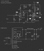
I guess that the EL84s draw about 40-45mA? The 12AT7 about 5-10?, that would make for about 100mA total. What looks interesting is that the choke is only specified at 50mA for both channels...
could someone please explain why a choke of 50mA rating is being used for an amp which draws 100mA current?
thanks......
I'm confused about the power supply...
Is the PS filter actually supposed to be a choke-input filter?
I just don't see how the power supply as shown in the schematic can possibly have a 300 V output using a 300-0-300 secondary and a CLC filter. Is the 47 µf input cap an error?
When I model the schematic in PSUDII using a Hammond 270HX (275-0-275 VAC) and a 100 mA current tap, I get ±363 VDC.
Am I missing something here?
Am I missing something here?
Did you use a tube rectifier in the simulation?
Hello there Maxro,
Yes, actually I did. After playing around with the software a bit, the problem appears to lie in how I entered in the transformer info. When I put 275v at 5% regulation I get approximately 318 VDC.
I'm also using a 5H choke (a Hammond 193H), which is bound to have less DC resistance than a 20 H job.
Yes, actually I did. After playing around with the software a bit, the problem appears to lie in how I entered in the transformer info.
When I put 275v at 5% regulation I get approximately 318 VDC. I'm also using a 5H choke (a Hammond 193H), which is bound to have less DC resistance than a 20 H job.
- Status
- This old topic is closed. If you want to reopen this topic, contact a moderator using the "Report Post" button.
- Home
- Amplifiers
- Tubes / Valves
- Rh84 Ptx