So I'm trying to play my 78s on my Rek-O-Kut and the tonearm wire has finally gotten past the "It'll work if you wiggle it" stage.
People on the web say that arm wire replacement is "easy". I should probably not comment on people who always say "it's easy".
What's stumped me is how to get to the headshell connector in the arm tube. I suppose that there must be some set screw or stake or something that holds it in place but whatever it is, it's also holding the headshell keeper collar in place, and I can't expose whatever is there under the collar.
Does anyone have any experience here?
Tanks
B
Rek-O-Kut Tonearm Rewire
I see this thread is almost dead. All the questions on arm rewiring have been answered in other forums. Hah! The only problem is they make little sense and there are no pictures. Some people say the pushed the plastic? fiber? whatever disc, that has the connector pins out the front by busing a wire up the back. Others say they heated the tube and pushed out the whole front part out from the back. The only thing wrong is that the descriptions of just what they pushed out vary too much, never a picture.
From what I can see, I think there is an isulation disc with connector pins in it. It is part of a smaller tube, that has the collar lock. That smaller tube seems press fit into the end of the tonearm. So, the solutions I have seen, do not describe in enough detail just what they removed. It was either the whole connector end, or just the isulation disc.
I can tell you that I jammed a coat hanger wire into the back end and pushed with all my might and could not get anything to move. I retried it a few times after heating the connector end. I gave up. I might have tried heating it more, but the other blogs described it as "plastic". So, has anybody had any luck? Any photos?
Same problem and still no solution....
Here is a long shot. Could it be threaded in but with an opposite handed thread, left hand rather than right hand. Occasionally you see LH threads in automotive applications Also, stuck threads sometimes need to be tightened a bit to break them free after which they come out normally. Another possibility is that there is some corrosion "welding" the part in there. Soaking in some penetrating oil may help. Good luck, sorry I have so little to offer.
BillG
Last edited:
Things weren't quite the way I remembered them, but I did re-wire a Micropoise and posted the adventure here.
Rek-O-Kut Micropoise re-wire - AudioKarma.org Home Audio Stereo Discussion Forums
I hope this is helpful and if I can answer any questions, please let me know.
Rek-O-Kut Micropoise re-wire - AudioKarma.org Home Audio Stereo Discussion Forums
I hope this is helpful and if I can answer any questions, please let me know.

Back a couple of weeks ago, maybe longer, I said I'd post about a Micropoise re-wire I did. Several guys, here and on another forum asked about that. I thought I had already done one and would just have to take pictures and explain the process, but I mis-remembered, another old guy moment, and had to figure things out from scratch.
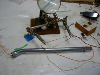
Disassembly involved removing the original interconnect wires, which were very stiff and I didn't want to use them. A screwdriver blade popped the black plastic fitting at the bottom of the pivot post and the internal wires were cut. The jam nut was removed and the entire arm was removed from the TT.
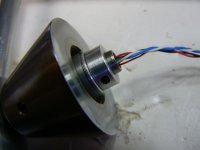
If you look closely at the photo of the bottom of the pivot, you can see a collar with a set screw and, above it, a very fine wire keeper clip. DON'T REMOVE that collar unless you enjoy chasing a large number of very small bearings. The keeper does have to come off if you want to remove the pivot from the cone shaped support, which makes things easier.
I removed the arm from the pivot. Take the head shell and CW off and back off the screws from the vertical bearings until the arm is free. There is a small spring and a plastic fitting under the VTF adjuster which have to be removed but, if you're careful, they come out easily. Pull the arm out from behind the pivot. The wires will come out of the pivot with the arm.
I found that working over a pie plate which could catch small parts was a very good idea.
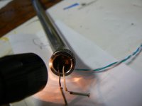
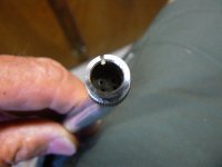
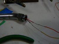
There is a rubber plug at the headshell end. There are four tiny pins that barely stand above the plug, but they can be removed with needle nose pliers or a blade like Xacto or a jeweler's screw driver. It takes time and it's a PITA, but it can be done. Expose the wires behind the pins, cut them leaving enough wire to grab for unsoldering, and then pull the wires out of the arm. If you're lucky and the pins are undamaged, use them for the new wires.
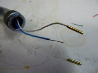
I wrecked a couple of the pins so I had to make new ones. I had some 1/16" brass tubing I bought in an Ace small parts section. I cut four pieces the same length as the original pins. I cut them a bit long, filed both ends flat, and beveled one end. Use a small, sharp point to open the hole in both ends.
I used mouse wire for the new wires. I cut and twisted two pairs, one CW and one CCW, in a hand drill. I used other mouse wire for the drag wire. I threaded two wires at a time back through the rubber plug. Pay close attention to polarity and wire color while you're doing this. I got it wrong at least once and that's really irritating. Fish the wire ends out from the hole at the pivot position. Strip and tin the drag wires and the new wire pair. Solder a butt joint between the drag wires and the new wire pair then carefully pull the new wires into the arm and out through the rubber plug. Repeat for the second new wire pair. Check to make sure polarity and color are correct. Remove the drag wire. Check and double-check polarity - it's very easy to get confused. Have the headshell nearby for reference.
Slip whichever kind pin you're using over the exposed tinned wire and solder. The insulation should bump the bottom of the pin. If you're using the brass pins, put the beveled end closest to the insulation. The bevel helps with the initial seating when installing the pins. Pull the wires back until the pins are touching the holes in the rubber plug. Use needle nose pliers to set the pins in the holes. The original pins should slide in easily. The brass pins are a tight fit. Move slowly making sure the wires don't crimp and set the pins until the heads are barely above the plug surface. Use a headshell to check pin height. They should be just high enough that the headshell mounts all the way back into the arm.
If you use resin for soldering, be sure to remove it before pulling wires or inserting pins. It's sticky and can bind parts just when you don't want that to happen.
With the headshell on, check continuity. If you're good, pull the wires at the pivot hole back into the pivot and re-assemble the arm. I found I had to insert the arm from the back of the pivot by putting the headshell collar end through first, then pushing the arm and pulling the wires at the same time until everything seated.
The process for the earlier S-120/160 arms is the same, but easier. Two of the photos are of an S-120.
I realize I probably should have taken more photos and I've probably not explained everything as well as I might. If there are questions or photos I can take, let me know.
I hope this helps.
Disassembly involved removing the original interconnect wires, which were very stiff and I didn't want to use them. A screwdriver blade popped the black plastic fitting at the bottom of the pivot post and the internal wires were cut. The jam nut was removed and the entire arm was removed from the TT.
If you look closely at the photo of the bottom of the pivot, you can see a collar with a set screw and, above it, a very fine wire keeper clip. DON'T REMOVE that collar unless you enjoy chasing a large number of very small bearings. The keeper does have to come off if you want to remove the pivot from the cone shaped support, which makes things easier.
I removed the arm from the pivot. Take the head shell and CW off and back off the screws from the vertical bearings until the arm is free. There is a small spring and a plastic fitting under the VTF adjuster which have to be removed but, if you're careful, they come out easily. Pull the arm out from behind the pivot. The wires will come out of the pivot with the arm.
I found that working over a pie plate which could catch small parts was a very good idea.
There is a rubber plug at the headshell end. There are four tiny pins that barely stand above the plug, but they can be removed with needle nose pliers or a blade like Xacto or a jeweler's screw driver. It takes time and it's a PITA, but it can be done. Expose the wires behind the pins, cut them leaving enough wire to grab for unsoldering, and then pull the wires out of the arm. If you're lucky and the pins are undamaged, use them for the new wires.
I wrecked a couple of the pins so I had to make new ones. I had some 1/16" brass tubing I bought in an Ace small parts section. I cut four pieces the same length as the original pins. I cut them a bit long, filed both ends flat, and beveled one end. Use a small, sharp point to open the hole in both ends.
I used mouse wire for the new wires. I cut and twisted two pairs, one CW and one CCW, in a hand drill. I used other mouse wire for the drag wire. I threaded two wires at a time back through the rubber plug. Pay close attention to polarity and wire color while you're doing this. I got it wrong at least once and that's really irritating. Fish the wire ends out from the hole at the pivot position. Strip and tin the drag wires and the new wire pair. Solder a butt joint between the drag wires and the new wire pair then carefully pull the new wires into the arm and out through the rubber plug. Repeat for the second new wire pair. Check to make sure polarity and color are correct. Remove the drag wire. Check and double-check polarity - it's very easy to get confused. Have the headshell nearby for reference.
Slip whichever kind pin you're using over the exposed tinned wire and solder. The insulation should bump the bottom of the pin. If you're using the brass pins, put the beveled end closest to the insulation. The bevel helps with the initial seating when installing the pins. Pull the wires back until the pins are touching the holes in the rubber plug. Use needle nose pliers to set the pins in the holes. The original pins should slide in easily. The brass pins are a tight fit. Move slowly making sure the wires don't crimp and set the pins until the heads are barely above the plug surface. Use a headshell to check pin height. They should be just high enough that the headshell mounts all the way back into the arm.
If you use resin for soldering, be sure to remove it before pulling wires or inserting pins. It's sticky and can bind parts just when you don't want that to happen.
With the headshell on, check continuity. If you're good, pull the wires at the pivot hole back into the pivot and re-assemble the arm. I found I had to insert the arm from the back of the pivot by putting the headshell collar end through first, then pushing the arm and pulling the wires at the same time until everything seated.
The process for the earlier S-120/160 arms is the same, but easier. Two of the photos are of an S-120.
I realize I probably should have taken more photos and I've probably not explained everything as well as I might. If there are questions or photos I can take, let me know.
I hope this helps.
Attachments
- Status
- This old topic is closed. If you want to reopen this topic, contact a moderator using the "Report Post" button.
- Home
- Source & Line
- Analogue Source
- Calling all Rek-O-Kut Experts ! ! !