Hi there,
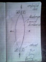
this bending transducer works much like the well known
devices from MBL. But instead of having the shape of a melon,
enclosing a volume totally, this device is open and can be
coupled into an enclosure.
There are 2 curved planar panels radiating.
With proper dimensions and wise choice of material,
fullrange operation and applicable dynamics should be
possible ...
What do You think guys ?
Cheers
Attachments
Nice idea LineArray
One other idea that you might consider: rather than the diaphragms being rectangular (as viewed from the front) - they could be trapezoidal i.e. different width from top to bottom. In this way it might benefit behaviour as a full range driver.
Keep thinking - you are definitely on an interesting track here.
Cheers,
Ed
Actually I was considering frequency response, plus the size & mass of the source, thinking that you might achieve a graded transition from high frequency to low frequency as the panel dimension increases.
However, I note your concern as to the behaviour of the voice coil if the two edges are not parallel - the whole assembly would experience additional forces in the vertical direction as well as the intended squeezing.
Ed
However, I note your concern as to the behaviour of the voice coil if the two edges are not parallel - the whole assembly would experience additional forces in the vertical direction as well as the intended squeezing.
Ed
Hi Ed,
i built a prototype 3 Years ago - veeery sloppy - just to
test the idea. Diaphragm and VC were very heavy.
Resonant frequency was subsonic, you could watch the decay
with your eyes when you tipped the "voice coil" open
circuited.
I was astonished that highs produced were "OK". I think
upper frequency limit is limited mainly by the width of the
diaphragm and the sonic speed of the material.
Distance from VC to VC limits frequency range.
My Proto had only one VC, the other end was fixed.
From my gut feeling i would say, that due to the sonic speed
of diaphragm material chosen, a quarter wavelength
(with longitudinal dispersion along the diaphragm) is
the maximum width (path from VC to VC) of the diaphragm.
With AL (c around 6000 m/s) lambda is 6000[m/s]/20000[1/s]
= 0,3 m. So max width would be 7,5 cm.
(...The 'Planot' device e.g. MUST have torsional vibration ...)
With two VC ( excitation from both sides) maybe width can be
doubled. If the upper frequency limit additionally is compromised
i consider a width around 20cm as practical limit for fullrange
operation, when Aluminium is used.
However beryllium is faster around 12000 m/s ...
Total mass seems not to limit upper frequency limit, but
overall efficiency, like things are with conventional dynamic
speakers.
Although trapezoidal shape may be interesting for other
puposes, it seems not necessary for reaching higher
frequencies IMO ...
What i intend is forced oscillation of the 1. bending mode
over the e n t i r e audio range. I hope, that with proper
dimensioning and damping, this is achievable ...
Cheers,
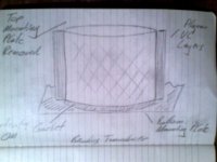
I have been thinking this a lot lately:
1) Radiation pattern is symmetric -> Good power response.
2) Magnets are not blocking sound propagation in the air.
3) Magnetic flux can be high.
4) If the tube is very long you can actually use it as a combined "speaker box and reflex pipe" which can be tuned to maximize bass untill the cut-off frequency. But I would use a bit stuffings inside?
One cone material that could be used is thin FR4 printed wired board which has relatively high sound velocity and easier to use than exotic metals. You can get FR4 from 100um thick and can etch voice coil on it.
ABJensen said:It is the principle in MBL isnt it.
Hi ABJensen,
as i said in my initial post the principle is much like
MBL. Shape and mode of motion is different and
my design is open, so you can couple the device to
an enclosure of arbitrary type, due to the TS Parameters
you want the device to adjust to ...
Regards
APi said:I have been thinking this a lot lately:
1) Radiation pattern is symmetric -> Good power response.
2) Magnets are not blocking sound propagation in the air.
3) Magnetic flux can be high.
4) If the tube is very long you can actually use it as a combined "speaker box and reflex pipe" which can be tuned to maximize bass untill the cut-off frequency. But I would use a bit stuffings inside?
One cone material that could be used is thin FR4 printed wired board which has relatively high sound velocity and easier to use than exotic metals. You can get FR4 from 100um thick and can etch voice coil on it.
Hi APi,
i think you got it, that are exactly the properties i see.
Using the device itself as reflex port is interesting, i thought of
it too. But the port changes its cross sectional area during
operation a little. To have a gasket only at the bottom would
cause asymetric motion. I personally would not use the device
itself as a port ... is it this you meant ?
Thanks for your material suggestion, this is why i posted my idea.
To get more ideas and motivation to build a more sophisticated
prototype.
A little stuffing inside was advantageous in my first prototype,
you are exactly right.
Seems you like the idea ...?
Regards
jzagaja said:Does it have roots in US patent 3686446, explored by Paddock later on?
Hi jzagaja,
i dont know the patent you mentioned. There may be
designs with similarities out there.
Even a lineaum is not too far away from that, but still
different.
I was inspired to go this direction when i played with 2
stamped Alu sheets in a model builder shop.
I squeezed them beneath my ears an heard some
(deep and loud !) bass sound. I was impressed.
Strangely i thought of building some kind of
musical instrument first.
The sheets made no "metal noise" due to the stamping and
the damping introduced by the skin of my hands ...
I often look at things asking "can it be used as a transducer ?",
it is some kind of illness i suffer from during decades.
I already knew the MBL transducers but i realized only later
on, that i would use the same principle of symmetrically bending
diaphragms.
However the MBL design encloses a rather small volume in
relation to the diaphragm size, which limits the Low Bass response possible.
Furthermore my design is much simpler to realise, i think.
Of cause MBL can use a conventional Voice Coil.
The stretched coil needed in my design, makes the motor
design maybe somewhat more complex.
There are several shapes of windings and Magnet assemblies
possible to achieve a large excursion within a homogenous
field.
But excursion of the coil will be signifficantly smaller than the
excursion in the middle of the diaphragm.
The motion of the coil is transformed into a larger excursion
of the diaphragm and the diaphragm can have a large area,
since you can make the device as high as you like (also by
stacking).
If higher vibrational modes can be avoided, and i see good
chances to achieve that, the transducer is simple and
has very good habits.
It can be used to make up a line source, which is a kind
of radiation i like very much.
Regards
I see the design capable of combining the advantages of
conventional dynamic drivers (large displacement volume)
with the advantages of other planar drivers (homogenoously
driven large area) without the need of stators or magnets
to be fixed in front of the radiating area.
The dream of an ideal but simple transducer ...
Where are the drawbacks ?
Up to now i see some technical difficulties, but it should be
possible to build a good device with "homebrew" methods.
Regards
Really?LineArray said:homogenoously driven large area
Furthermore: What about resonances?
I would reconsider the principle.
Hi tiki,
i am sure, you are able to explain to us why it
cannot work !
Of cause velocity is unevenly distributed over the
area. Thats similar to a conventional ribbon tweeter.
As in German "Hifi Forum" i cannot see anything new
in your post, nothing that has not been mentioned in the
posts before and nothing constructive ...
Uneven distributed excursion and diaphragm velocity has
been already mentioned and is crystal clear from the
sketch. The need of taking care of higher vibrational modes,
which are undesired has already been mentioned.
Fortunately, those kinds of postings are very unusual
in diyAudio.com .
When unfamiliar with the principle, please read the documents
from MBL. Those transducers come very close to my design,
as already mentioned.
When i want to talk to someone who behaves emotional
and destructive
- and furthermore lacks the ability to remember what
was said 2 minutes before -
i would not post here about Audio Stuff but talk to one
of my former girlfriends tiki.
Understand ?
To the other members: Yes we know each other already.
Cheers
Hi jzgaja,
i am not quite shure if warnaka is comparable.
The warnaka speaker excites transversal waves directly.
I would think that suppresion of higher order modes is
not possible using that kind of excitation.
In my (and MBL's) design excitement is longitudinal.
Transversal displacement here is a consequence of the forces
acting longitudinal through the diaphragm.
Sonic velocity is much higher in longitudinal direction than
propagation of transversal waves along a thin sheet ...
Furthermore the displacement in the excitation point of
the warnaka design equals the displacement of the VC.
In the design i proposed, there is some leverage between
VC and the median axis of the diaphragm ...
My and MBL's design is not directly comparable to bending wave
transducers like Manger or Göbel or Walsh (Ohm) !
There is a distinction between "bending wave transducers"
( like the former mentioned) and "bending transducers".
A bending transducer does not rely on transversal wave
propagation but on deformation to displace a volume of air.
The Heil Air motion Transformer e.g. could be interpreted as
bending Transducer IMO, because the foil changes its
s h a p e .
Even the MBL and my approach relies on the oscillation between
shapes of different volume.
Do not mix "bending wave" and "bending" transducers.
A bending wave transducer normally uses a foil or a sheet with
high modal density in the usable frequency range
(Thereby utilizing a material with low sonic speed
like Manger).
In my design the structure would be stiff and lightweight with
the use of a material with sonic speed as high as possible.
The forced excitation of the 1. bending mode is
comparable to the pistonic motion of a conventional
dynamic speaker below the frequency where cone breakup
occurs. And ideally you do not want cone breakup over
the entire audio range.
Kind Regards
Hi Oliver,
before accusing me of emotionality, keep in mind, that you still have an idea of an driver (and a "sloppy prototype"), my approach is already working and patented instead (Oliver Mertineit isn't listed at depatisnet at least). Other guys are able to review such simple sketches too.
If you aren't ready for factual criticism, avoid writing here.
I still believe, that you did not get the point of:
"homogenoously driven large area"
or, you mixed the terms. This is independent of the possible functionality and sense of the approach presented here.
Maybe, your spelling style is not very suitable for getting substantive help here.
Regards,
- Status
- This old topic is closed. If you want to reopen this topic, contact a moderator using the "Report Post" button.
- Home
- Loudspeakers
- Planars & Exotics
- Sketch For Bending Transducer (Prototype already built)