Well, if you're interested (or feel bored ") ) you can read a lot on proper grounding techniques.
) you can read a lot on proper grounding techniques.
My few cents are:
A ground plane is for the lazy engineer that doesn't care (or does not want to care) about where the return currents flow. So a ground plane allows them to find the path of minimum impedance. Drawback: adds capacitance (order of pF) to every circuit node.
If you know the ins and outs of the electrical circuit (currents) you can do a star ground which has also the nice advantage that you can use this pcb-side also for routing other signals.
Keep power and signal ground separate in any case. Keep digital and analog separate.
Have fun, Hannes
) you can read a lot on proper grounding techniques.My few cents are:
A ground plane is for the lazy engineer that doesn't care (or does not want to care) about where the return currents flow. So a ground plane allows them to find the path of minimum impedance. Drawback: adds capacitance (order of pF) to every circuit node.
If you know the ins and outs of the electrical circuit (currents) you can do a star ground which has also the nice advantage that you can use this pcb-side also for routing other signals.
Keep power and signal ground separate in any case. Keep digital and analog separate.
Have fun, Hannes
Hi...thanks for the replies.
If I go the ground plane route, by separating power and signal grounds, it that by physical distance?
I see on Jan dupont site and his PCBs he uses ground planes throughout with success. the input grounds are at the other end of the PCB to the power gound in some cases...is that what is meant by separation?
rob
If I go the ground plane route, by separating power and signal grounds, it that by physical distance?
In general this is not necessary. With separate I mean electrically separate. Connect each ground separately to your ground star, not on the pcb. This avoids voltage drops in the cabling to your pcb due to large currents being sent into power ground.
For a phono stage it won't hurt to keep an eye on physical distance as well; but I'm talking more about avoiding putting them next to each other than about keeping them on opposite sides of the board
Anyway the current demands in a phono stage are very small in general.
Have fun, Hannes
robmil said:I'm in the process of laying out the phonoclone. Is it best to use a ground plane or star? If a ground plane where does the 0 volts connect on this plane?
Hi Rob,
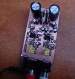
I've been working on one that uses an AC wall adapter with the regulated supply on the board with the preamp and ran into some hum that I think I have now fixed. I'm not sure how yours will be but here's what I found I had to do. I separated the supply ground with a 10 ohm resistor (R10 in the pic below). This cut the hum to near nothing. I'm also looking for clues as to how to reduce this even further.
Attachments
A ground plane is for the lazy engineer that doesn't care (or does not want to care) about where the return currents flow.
This has nothing to do being lazy!
Working with small signals that requires 60dB (1000 times) amplification or more, a ground plane is must.
And like jackinnj says, the ground plane should be connected to the PSU ground terminal.
This avoids voltage drops in the cabling to your pcb due to large currents being sent into power ground.
Where do you find these voltage drops and large currents in a phono stage? Maybe you should concider a redesign to match voltage and current to the actual job...........
One square centimeter area = 3 pF => a trace over groundplane = less.h_a said:Drawback: adds capacitance (order of pF) to every circuit node.
34 pF/m with a 1 mm wide trace according to
this calculator
Fraction of a pF is never a problem in these non-high impedance circuits.
One thing to care about is the feedback path though.
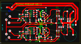
well, I'm going with Jan's ideas about ground planes. I spoke to a designer at a known pro-mixer company yesterday and he said that I 'really' need a ground plane. With digital I would need 3-4 planes - 1 digital, 1 analog, 1 ground and 1 power or sometimes you can get away with 1 plane that carries analog and digital signals BUT these need to be physically separated.
So, I'm going ground plane....BUT how?
Does my input lead from the RCA go to the PCB? Do all grounds (RIAA, grounds from ICs, power) all go the the plane at their nearest point like you see on Philips CD players.
So, I'm going ground plane....BUT how?
Does my input lead from the RCA go to the PCB? Do all grounds (RIAA, grounds from ICs, power) all go the the plane at their nearest point like you see on Philips CD players.
robmil said:MJL - Is connecting a 10R resistor between PSU Gnd and Audio Gnd common practice as I've never seen it done before. Do you use a 5 watt resistor for this? If the resistor value rises (heat etc) what happens to your RIAA accuracy?
Rob.
Hi Rob,
I don't know what is common, but I'll try nearly anything to eliminate hum. I'm just using a 1/4 watt resistor as the current would be very tiny, so no worries about it heating up. Shoot, my regulators don't even get warm.
I have gone through several changes and board revisions (getting quite a stack of used boards) and I'm nearly there. I have a ground plane on the bottom layer that is connected to the power supply common. This handles all of the decoupling. I then have the signal ground separated from this by the small value resistor. This picks up the shunts from the filters as well as the audio ground.
I just etched and drilled board #5, ready to stuff and test. Hopefully it's a winner this time.
Ah, nothing like a morning with my harmless little post torn apart in true DIYAudio-style
Whatever you gentlemen prefer, however at least reading the full post before replying would be nice, eh?
as in my very same post:
My post was intended to give simple advice to a novice and not to show-off expertise (which I anyway don't have).
Nevertheless, I can't resist to post a snipet of "A Practical Guide to High-Speed Printed-Circuit-Board Layout" By John Ardizzoni [analog.com]
Pick your poison
Of course I agree that ground planes (and power planes) are necessary for RF-and digital applications (fast rising edges), however in audio I prefer a clean star-ground and the possibility to use the 2nd side for routing other signals.
Now go and tell me there's a simple answer to grounding.
Have fun, Hannes
EDIT: found another Maxim-appnote with general advice (well, it's about cell phones...doesn't P-A work for a cell-phone company? )
http://www.maxim-ic.com/appnotes.cfm/an_pk/4079
Whatever you gentlemen prefer, however at least reading the full post before replying would be nice, eh?
ACD Where do you find these voltage drops and large currents in a phono stage? Maybe you should concider a redesign to match voltage and current to the actual job...........
as in my very same post:
Anyway the current demands in a phono stage are very small in general.
My post was intended to give simple advice to a novice and not to show-off expertise (which I anyway don't have).
Nevertheless, I can't resist to post a snipet of "A Practical Guide to High-Speed Printed-Circuit-Board Layout" By John Ardizzoni [analog.com]
...A ground plane acts as a common reference voltage, provides shielding, enables heat dissipation, and reduces stray inductance (but it also increases parasitic capacitance). While there are many advantages to using a ground plane, care must be taken when implementing it, because there are limitations to what it can and cannot do.
Nevertheless, there are exceptions, and sometimes less ground plane is better. High-speed op amps will perform better if the ground plane is removed from under the input and output pads. The stray capacitance introduced by the ground plane at the input, added to the op amp’s input capacitance, lowers the phase margin and can cause instability. As seen in the parasitics discussion, 1 pF of capacitance at an op amp’s input can cause significant peaking. Capacitive loading at the output—including strays—creates a pole in the feedback loop. This can reduce phase margin and could cause the circuit to become unstable.
Pick your poison
Of course I agree that ground planes (and power planes) are necessary for RF-and digital applications (fast rising edges), however in audio I prefer a clean star-ground and the possibility to use the 2nd side for routing other signals.
Now go and tell me there's a simple answer to grounding.
Have fun, Hannes
EDIT: found another Maxim-appnote with general advice (well, it's about cell phones...doesn't P-A work for a cell-phone company?
)1. Establish a Continuous Ground Plane for Digital Circuits
2. Keep Ground Currents Separate
3. Use the Star Grounding Technique for Analog Circuits
4. Maximize the Effectiveness of Bypass Capacitors
5. Flood All Unused PCB Area with Ground
http://www.maxim-ic.com/appnotes.cfm/an_pk/4079
robmil said:That sounds interesting. I'll have to try it.
I highly recommend it. I just tested the latest board and I think I have a winner. I used a ground plain on both top and bottom, as described above. Sitting out in the open (no chassis yet) I tested it with RMAA for noise level and it is below -75db. I confirmed this with Adobe Audition, recording the output without a record playing.
My turntable is not on a very solid stand and it has a computer close by with a rather noisy fan going so this figure might be lower. Compare with the previous board version, I have made a serious drop in noise. The noise level of the previous version tested at -43db.
Attachments
- Status
- This old topic is closed. If you want to reopen this topic, contact a moderator using the "Report Post" button.
- Home
- Amplifiers
- Solid State
- PCB layout for phonostage