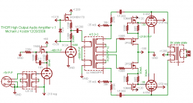
Here is an amplifier project I'm starting to put together. It uses all thoriated tungsten filament tubes,
and it's a high power amplifier, hence the name "THOR". Attached is the current working schematic.
Concepts:
- High power, high fidelity audio amplifier using transmitting tubes
- Beam tetrode push-pull output in class AB2 with local plate-grid feedback (O.H. Schade style)
- 2 stage DC driver in class A2 "zero bias" with parafeed transformer coupling to output stage
- MOSFET active anode loads and grid drive buffers to enable linear operation in A2/AB2
- Reasonable power efficiency to allow operation from a single 120 volt AC circuit < 1500W max
- Stable operating points and rated for CCS
Theory of operation:
The driver section is a 2-stage direct coupled amplifier with MOSFET active loads and parallel
feed output. The first stage is an 801A operated in zero-bias. The signal source must be capable
of operation into 600 ohms in order to supply <1mA of grid current with low distortion.
~5V-10V p-p input signal is needed for full output power. The stage voltage gain is about 8.
The 801A operates into a stacked fixed-reference voltage follower/anode load. This
functions like a gyrator and mu-follower with a fixed DC bias to the grid if the next stage. The
gyrator provides a high impedance load to the 801A anode and the mu-follower provides
low impedance drive for linear grid swing of the 3C24 in class A2.
The 3C24 driver stage also operates in near zero-bias class A2 and also works into an active
load. This stage acts more like a SRPP or totem-pole with the 3C24 and the MOSFET driving
opposite current swings into the load. This results in effective output impedance of Rp/2 or a little
below 5K ohms using the 3C24 to "play through" the finite inductance and capacitance of the IT.
This stage needs a huge voltage swing to allow the output stage to use local feedback to emulate
low mu, low Rp triode operation.
The output of the driver is parallel fed into the LL1660S/PP interstage transformer. The audio
signal here is up to 950V P-P for a single ended drive stage or up to 1650V P-P for a push-pull
drive stage using a pair of 3C24s. (The push-pull drive stage option mirrors the entire 2 stage
driver for each channel). The stage voltage gain is about 23, for a total voltage gain of about 184
from input to IT primary.
The output section uses a pair of 4-65As in class AB2 push-pull. The basic topology is as shown
in O.H Schade's "Beam Power Tubes", having plate feedback AC coupled to the interstage drive
transformer. Grid drive current comes from a separate power supply through the class A totem
pole followers. These have about 10R to the positive supply and 100R to the negative supply of
effective DCR, and isolate grid current from the drive stage and feedback network. Depending on
the amount of drive voltage available (SE or PP drive stage) the local plate-grid feedback results
in an effective "triode equivalent" Rp of 500-800 ohms driving into 2K impedance, for a damping
factor of 2.5:1 or 4:1. Voltage swing is about 900Vp per anode into 2K for about 200W output
power at the anodes.
Operating all of the filaments at fixed potential allows using SMPS with external chokes to power
the hungry TT emitters.
I just found some output transformers I've been waiting on to proceed with this foolish endeavor.
Now where would I find a worthy power transformer and chokes? I could wire the secondaries of
three 480V/1A control transformers in series and use a bridge rectifier... full signal on both channels
is 550 mA at 1200V. Hmm... 660W in, 400W out... 60% plate efficiency, 65W per 4-65A. Check.
My first decision to maket is SE drive or PP? I'm favoring the PP drive stage because it enable more
local feedback in the output stage and a lower output impedance. However, the SE drive stage
may give the amp a more SE-like harmonic signature and save about 100W of idle power. The PP
drive stage is a more manly option and results in 16 bright filaments, counting the 4 damper diode
B+ rectifiers.
I'm thinking about building it vertically on a trolley ;-) so as to
have room for proper power supplies.
Cheers,
Michael
Attachments
Its all followers and current sinks here,
no voltage amplification happening in
the land of Sand.
I count two Schaded Pentode Triode
emulators. And one AntiTriode, slaved
to a real Triode. No signal processing
is happening outside of Hollow Glass.
Itch if you want to... All his cheats are
in order, you aren't going to hear them.
no voltage amplification happening in
the land of Sand.
I count two Schaded Pentode Triode
emulators. And one AntiTriode, slaved
to a real Triode. No signal processing
is happening outside of Hollow Glass.
Itch if you want to... All his cheats are
in order, you aren't going to hear them.
The 39K's are a resistive load. And the Schade feedback would
make the 270K plate resistor look to be another 31K in parallel
to GND. Thats one end of the winding...
The other (flapping?) end, is 100R into an insulated Gate with
a following voltage on the other side. That ought to appear as
nearly infinate impedance. You might have a point.
make the 270K plate resistor look to be another 31K in parallel
to GND. Thats one end of the winding...
The other (flapping?) end, is 100R into an insulated Gate with
a following voltage on the other side. That ought to appear as
nearly infinate impedance. You might have a point.
kenpeter said:The Pentodes Schade back to an EmMU of ~7.9 .
Yet 420 P-P * 7.9 is quite a bit more than B * 2
max possible plate swing...
Or was it only 210 per winding you meant for
that side of the IT? That would be consistent
with the swing you quote for the grid drives...
Hmm time to check my work again. I get an actual VA of about
-8 grid to plate and a Schade mu of about 4 when you add about
210 Vpp of feedback to the 210 Vpp grid swing. That's how I got
the 420Vpp per secondary. Actually I think it makes more sense
to talk about peak voltage when discussing class B operation,
but I guess it depends which side of the phase splitter you're on.
Here's the load line
Michael
Attachments

Boris_The_Blade said:I have a funny feeling you may get some frequency response funkyness with the LL1660 without a resistive load at least on the secondary. Kinda flappin' in the wind there.
You're right, I need to put some kind of load on that. I wonder if
it would be feasable to inject current feedback from the output,
to simulate the speaker load on the SET drive stage? At least a
resistor though.
Thanks,
Michael
Hi Tony,
The 38K resistors load the plate feedback loop but not the IT
secondary winding, which can possibly ring problematically. I've
not used this transformer before so I can't speak from experience.
Interestingly, Lundahl give the frequency response results for
the LL1660S/PP as 20Hz-25KHz with 15K source impedance and
an unloaded secondary.
Cheers,
Michael
210VP-P G1 swing seems completely off the
guideline charts.... And inconsistant with your
proposed loadline. But it might be real enough.
"I get an actual VA of about -8 grid to plate"
Huh? What? Sorry, you lost me completely...
"and a Schade mu of about 4"
So I forgot: No Pentode will have infinate
voltage gain. Was merely your ratio 7.9
of resistances in the feedback network....
Neglecting to degrade my figure properly.
If you'd Schaded an output stage around
those cool new IGBTs, my guessed EmMU
mighta been a bit closer your measured...
But sandy processing of signal voltage
seems not the point of today's exercise.
Tony said:isn't the 38k resistors going to the -35v adjust the load? it should be at ground or zero as far as ac is concerned anyway is it not?
Yeah, but again, thats only one end of the winding...
Nothing at the other end of the winding completes a
circuit that might allow that 38K to be seen as a load.
What happens if we move 38K to the other end?
Considering 270K / Mu to a virtual GND, does this
complete a circuit of 105K load at each secondary?
Does this not also present the desired sample of real
load across the IT, such that the single ended primary
circuit might better participate in giving it character?
kenpeter said:210VP-P G1 swing seems completely off the
guideline charts.... And inconsistant with your
proposed loadline. But it might be real enough.
"I get an actual VA of about -8 grid to plate"
Huh? What? Sorry, you lost me completely...
"and a Schade mu of about 4"
So I forgot: No Pentode will have infinate
voltage gain. Was merely your ratio 7.9
of resistances in the feedback network....
Neglecting to degrade my figure properly.
If you'd Schaded an output stage around
those cool new IGBTs, my guessed EmMU
mighta been a bit closer your measured...
But sandy processing of signal voltage
seems not the point of today's exercise.
So if the bias voltage is -40 (ignoring the -30 shown on the sch)
and the peak grid voltage is +65, is that not 210V peak-to-peak?
This is a class AB loadline so really it's 105V peak signal voltage
on each grid. To further confuse things, RCA specifies peak
grid-to-grid signal voltage on one datasheet (210V) and Eimac
specifies peak grid signal voltage (105) on their data sheet for
the same op point. If the peak grid voltage is 105 volts and the
corresponding plate swing is -800V, then the voltage gain is
about -8. Reducing the gain by half using local feedback results
in an effective triode mu of 4. It's not exactly mu because mu is
independent of load but I think it still works out. If the mu is 4
and the gm is 4000, then is the effective Rp not about 1000 ohms?
If I tried to run IGBTs orange they wouldn't last long now would they...
;-)
Cheers
Michael
Michael Koster said:
If I tried to run IGBTs orange they wouldn't last long now would they...
50/50 StackOde... 3400V Max... Only half as orange...
Merely a matter of throwing enough sand on the fire.
JoshK said:Interesting. I don't confess to understand the driver one bit. Boat anchor territory 4sure.
You driving electrostats?
Each OPT is a boat anchor. The finished amp ought to hold a 40
footer in most weather.
I'll be driving 2-way horns to start with, ported LaScalaVOTT with
Altec 299/Mantarays on top. It should push 130db peak levels.
The idea is great tube sound in medium size venues and outdoor.
The connections labeled "CCS" go to a floating supply like a dual
bobbin transformer with minimal capacitance to ground. a 12V battery
might be a great alternative as Ken suggests. This allows the
6N170 to work as an active pull-up current source when the tube starts
sinking less current due to the instantaneous signal voltage.
Cheers,
Michael
Hi Michael,
very challeging project!
In your place I would shift the phase splitting.
I would load a VT25 (at the input) with the 1660S/10ma in SE to PP mode (2.25 : 2+2).
The VT25 woud be run at 425V /18 mA.
From specifications, the transformer would work at its recom. operating point ( 0.9T ) and 42H primary inductance would work, IMO, very well for the VT25.
Its 5K internal resistance would not change very much the low end frequency response while helping to smooth the high frequancy peaking.
With 1V on the grid of the VT25 you should get approx. 2,5+2,5V.
In this way you also would not need any power preamplifier....
Cheers,
45
- Status
- This old topic is closed. If you want to reopen this topic, contact a moderator using the "Report Post" button.
- Home
- Amplifiers
- Tubes / Valves
- High-power amplifier using transmitting tubes