Some of you may have seen the "Blind Listening Tests & Amplifiers" thread in the Solid State Amplifiers forum. One of the things discussed there is null difference testing. Null testing is generally used one of the following ways:
Null testing can be used to compare the errors and distortions produced by two devices under test. You simply subtract the gain-matched ("nulled") output of the two devices from each other. If you get a deep null, a strong argument can be made the two devices will be indistinguishable in listening tests.
Null testing can also be used to compare the input to a device with the output of that device. If you subtract the gain-matched ("nulled") output from the input, what you're left with is ALL distortion and errors produced by that device. The resulting null signal can then be quantitatively measured in various ways (i.e. average level, spectral content, etc.). You can also listen to it if you want to subjectively evaluate the distortion products, etc.
It should be stressed that null testing allows the use of ANY kind of test signal ranging from real music to pink noise to sine waves. If you're testing an amplifier, you can test it driving real-world speakers.
Null testing allows the device under test to be used exactly as it would be when listening to music in your system. SO MOST OF THE USUAL ARGUMENTS AGAINST CONVENTIONAL MEASUREMENTS DON'T APPLY TO NULL TESTING. It measures ANY kind of distortion or errors produced by the device including frequency response deviation, phase shift, THD, IMD, TIM, etc.
A famous example using null testing was the Carver Challenge in Stereophile. Bob Carver challenged the editors of Stereophile they would not be able to hear any difference between a $700 Carver amp and whatever amp they wanted to provide as a reference amp. Stereophile chose a very well regarded high-end tube amp with a five figure price tag. They were very certain they would win the challenge.
Bob Carver spent a few days nulling his $700 Carver amp against the reference amp. He added some series resistance to the output and tweaked the feedback loop in the Carver. He claims he ultimately achieved a -70db null between the two amplifiers. The editors at Stereophile listened for two days and finally gave up--they couldn't hear any difference!
The Carver Challenge, IMHO, further validates null testing as a very powerful tool for audio design. The technique was first published by Baxandall in 1977 and then again in 1986 by David Hafler. You can find diagrams of the null setups proposed by both authors in this link:
http://www.dself.demon.co.uk/subjectv.htm
I've attached a GIF of a simple null setup that most DIY folks can easily try. Ideally, the 50 ohm pots should be multi-turn (trimpots are fine) so you can get an exact null but single-turn pots can also work.
A test CD with a pink noise track makes an ideal signal source. Pink noise is a dynamic signal that contains all frequencies in the audio band in roughly the same proportions as real music. You can, of course, also use real music and sine wave test tracks.
You simply hook a sensitive AC voltmeter across the null terminals, set a reference level at one of the reference points and then adjust the pots for the lowest voltage at the null terminals.
I put together the setup shown in the diagram and got the following null results:
Reference Level: 10 volts rms (after the divider network)
Null Level 100hz sine wave: 1.8mv (-75db)
Null Level 1khz sine wave: 2.0mv (-74db)
Null Level 20khz sine wave: 9.1mv (-61db)
Null Level 100hz square wave: 3.5mv (-69db)
Null Level Pink Noise: 9.8mv (-60db)
Null Level Music (peak hold): 8.1mv (-62db)
The above measurements compare the left and right channels of the preamp and power amp signal chains. Any deviation between them is at least 60db below the audio signal. As you can see, the channel match is over 10db worse at high frequencies--probably due to component tolerances in the feedback loop and board layout issues in the preamp and amp. NULL TESTING IS VERY SENSITIVE!
Now, just for fun, I swapped out ONE of the interconnects between the pre-amp and power amp. I used a cheap $2 RCA thin patch cord in one channel and a $140 KimberKable "Hero" in the other channel. I repeated the null measurements and they were all within 1db of the ones listed above.
When I have more time, I may try to perform a spectral analysis of the null signals with both cables. But just looking at the depth of the null, I'd have to say the cheap interconnect and the expensive Kimber interconnect are essentially equal and hence I doubt anyone would be able to hear a difference in a proper blind listening test.
In addition to testing cables, this setup can also be used to compare changes to an amp or preamp. You can change capacitors, resistors, etc., in one channel and compare the null results. If there's no significant change, it's a safe bet the change you made didn't make an audible difference.
Some things to be careful of... You ideally need a meter that's reasonably flat out to 20khz for the most accurate measurements. Many cheap DMMs are not. If you want to view the signal on a scope or perform a spectral analysis, be careful of grounding issues. The 1k resistors should prevent any amplifier damage if you ground one of the outputs, but you will get invalid measurements. Be careful of ground loops, etc.
Attachments
Re: The "famous" null...
True, that's why I posted this link:
http://www.dself.demon.co.uk/subjectv.htm
It has diagrams of both the Baxendall and Hafler test setups (both of which are designed for amplifiers, not cables).
I only wanted to show a simple way to compare cables, or capacitors, or resistors, or whatever, without needing two amplifiers or a fancy setup.
Tube_Dude said:Hi Nw
In your set up we can only find diferences between chanels...but nothing about the intrinsic linearity of each one of the chanels!!!
True, that's why I posted this link:
http://www.dself.demon.co.uk/subjectv.htm
It has diagrams of both the Baxendall and Hafler test setups (both of which are designed for amplifiers, not cables).
I only wanted to show a simple way to compare cables, or capacitors, or resistors, or whatever, without needing two amplifiers or a fancy setup.
Flawed Null Difference Testing
It is described in the Radiotron Designers Handbook too I think - late fifties.
Virtually ALL dmm's are NOT flat to 20kHz.
Also, virtually ANY amplifier will behave and measure perfectly into 2k ohms load impedenece, and your test setup is not duplicating real world conditions, except for line level gear.
The more correct method for power amplifiers is to use a Y-cable to feed both inputs, load both outputs with a loudspeaker (or simulated loudspeaker load), and then take a look at the amplifer output channel differences.
To find an arbitary null, a balance control shoud precede the amplifier inputs, instead of using a Y-lead.
Headphones across the amplifier output active terminals is useful for listening tests.
Different cables between the Y-lead and amplifier inputs ought to reveal more differences than your diagram.
Eric.
Null testing can be used to compare the errors and distortions produced by two devices under test. You simply subtract the gain-matched ("nulled") output of the two devices from each other. If you get a deep null, a strong argument can be made the two devices will be indistinguishable in listening tests.
It is described in the Radiotron Designers Handbook too I think - late fifties.
Some things to be careful of... You ideally need a meter that's reasonably flat out to 20khz for the most accurate measurements. Many cheap DMMs are not. If you want to view the signal on a scope or perform a spectral analysis, be careful of grounding issues. The 1k resistors should prevent any amplifier damage if you ground one of the outputs, but you will get invalid measurements. Be careful of ground loops, etc.
Virtually ALL dmm's are NOT flat to 20kHz.
Also, virtually ANY amplifier will behave and measure perfectly into 2k ohms load impedenece, and your test setup is not duplicating real world conditions, except for line level gear.
The more correct method for power amplifiers is to use a Y-cable to feed both inputs, load both outputs with a loudspeaker (or simulated loudspeaker load), and then take a look at the amplifer output channel differences.
To find an arbitary null, a balance control shoud precede the amplifier inputs, instead of using a Y-lead.
Headphones across the amplifier output active terminals is useful for listening tests.
Different cables between the Y-lead and amplifier inputs ought to reveal more differences than your diagram.
Eric.
Re: Flawed Null Difference Testing
My Fluke 189 is. As are many analog meters designed for audio use. Also, keep in mind, we're generally looking for RELATIVE differences here, so even if the meter is down a few db at 20khz if you're just comparing two nulls, it will still work just fine.mrfeedback said:Virtually ALL dmm's are NOT flat to 20kHz.
The particular example I outlined was for testing cables so you actually want the amplifier to measure better so that the null test is more sensitive to cable differences. Even with a 2k load, amplifiers are far from perfect where null testing is concerned. As I stated in the previous post, the two diagrams in the link are better suited for testing power amplifiers. You can also, of course, simply attach speakers and use the cable testing circuit as well.mrfeedback said:Also, virtually ANY amplifier will behave and measure perfectly into 2k ohms load impedenece, and your test setup is not duplicating real world conditions, except for line level gear.
The more correct method for power amplifiers is to use a Y-cable to feed both inputs, load both outputs with a loudspeaker (or simulated loudspeaker load), and then take a look at the amplifer output channel differences.
Still Not Valid Testing.
My Fluke 77 is flat to about 500Hz.
Most cheap Asian DMM's are similarly bad.
Your own test results show worsening at high er frequencies.
Nope, you are still not testing under real world conditions, and your test will be less sensitive.
A lot of gear spits stuff back up the interconnect.
This is a big reason that interconnects can sound so different, and it gets worse with increasing load on the amplifier.
To be picking real differences the amplifier must be loaded as in actual useage.
This is to help you to be sure that you are making completely valid tests, in order to gain valid results.
Eric.
My Fluke 189 is. As are many analog meters designed for audio use. Also, keep in mind, we're generally looking for RELATIVE differences here, so even if the meter is down a few db at 20khz if you're just comparing two nulls, it will still work just fine.
My Fluke 77 is flat to about 500Hz.
Most cheap Asian DMM's are similarly bad.
Your own test results show worsening at high er frequencies.
The particular example I outlined was for testing cables so you actually want the amplifier to measure better so that the null test is more sensitive to cable differences. Even with a 2k load, amplifiers are far from perfect where null testing is concerned. As I stated in the previous post, the two diagrams in the link are better suited for testing power amplifiers. You can also, of course, simply attach speakers and use the cable testing circuit as well.
Nope, you are still not testing under real world conditions, and your test will be less sensitive.
A lot of gear spits stuff back up the interconnect.
This is a big reason that interconnects can sound so different, and it gets worse with increasing load on the amplifier.
To be picking real differences the amplifier must be loaded as in actual useage.
This is to help you to be sure that you are making completely valid tests, in order to gain valid results.
Eric.
Re: Still Not Valid Testing.
I'm also not aware of any way the load on an amplifier can "spit stuff back up the interconnect" or otherwise change the load at the input. If you have a technical explanation for that, I'd love to hear it.
But if you'd like, just hook up speakers and perform the same test. The cable test will actually be LESS sensitive that way, but suit yourself.
My own test results show a HIGHER null signal at high frequencies. If the meter was rolling off, it would record a LOWER voltage. You don't seem to understand what's going on here. The Fluke 189 is spec'd at 1.4db down at 100khz and it does considerably better in real life.mrfeedback said:My Fluke 77 is flat to about 500Hz.
Most cheap Asian DMM's are similarly bad.
Your own test results show worsening at high er frequencies.
Nope, you are still not testing under real world conditions, and your test will be less sensitive.
A lot of gear spits stuff back up the interconnect.
This is a big reason that interconnects can sound so different, and it gets worse with increasing load on the amplifier.
To be picking real differences the amplifier must be loaded as in actual useage.
This is to help you to be sure that you are making completely valid tests, in order to gain valid results.
I'm also not aware of any way the load on an amplifier can "spit stuff back up the interconnect" or otherwise change the load at the input. If you have a technical explanation for that, I'd love to hear it.
But if you'd like, just hook up speakers and perform the same test. The cable test will actually be LESS sensitive that way, but suit yourself.
Tube_Dude ultimate null test...reprise...
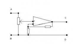
To make more clear my null test i attach a schematic of it..
It can work with a signal generator or with a CD for real musical conditions of operation...and with a reactif load attached...
Connect a signal generator or a Compact Disc Player to points AB.
Connect your favorit loudspeaker to CD.
And connect to points AC :
-A DNM for to read the null
-A osciloscope for to see the null
-A second amplifier or a signal tracer fot to ear the null...")
With the pot tourning from the minimum...you will find a point were the voltage between AC is at minimum...this is the null point!
It will show any type of distortion...because it will show the diference between input and output...and a zero diference will be the limit!!!
So easy and so real...
To make more clear my null test i attach a schematic of it..
It can work with a signal generator or with a CD for real musical conditions of operation...and with a reactif load attached...
Connect a signal generator or a Compact Disc Player to points AB.
Connect your favorit loudspeaker to CD.
And connect to points AC :
-A DNM for to read the null
-A osciloscope for to see the null
-A second amplifier or a signal tracer fot to ear the null...
With the pot tourning from the minimum...you will find a point were the voltage between AC is at minimum...this is the null point!
It will show any type of distortion...because it will show the diference between input and output...and a zero diference will be the limit!!!
So easy and so real...
Attachments
nw_avphile said:
My own test results show a HIGHER null signal at high frequencies. If the meter was rolling off, it would record a LOWER voltage. You don't seem to understand what's going on here. The Fluke 189 is spec'd at 1.4db down at 100khz and it does considerably better in real life.
Your test results......
Null Level 100hz sine wave: 1.8mv (-75db)
Null Level 1khz sine wave: 2.0mv (-74db)
Null Level 20khz sine wave: 9.1mv (-61db
Hmmmmm, 100Hz-1.8mV, 1kHz - 2.0mV, 20kHz-9.1mV = rising error voltage/frequency despite DMM droop/frquency does it not ?.
So who is misunderstanding what ?.
I'm also not aware of any way the load on an amplifier can spit stuff back up the interconnect; or otherwise change the load at the input. If you have a technical explanation for that, I'd love to hear it.
In a conventional input diff-pair stage, if the current source is not perfect, and the transistor gains not linear, then a DYNAMICALLY varying input impedence will eventuate, and due to stored energy, stuff will spit back up the interconnect, and confuse the previous line output stage.
This causes ringing, and is most evident on CDP-Preamp connections, and much due to +20kHz junk.
Preamp-Power amp connections suffer this ringing too.
The electrical characteristics of the interconnect can have great bearing here, and are an explanation for quite wildly differing sonics due to interconnect changes.
Digital input stages can spit stuff back up the line too - just ask Jocko.
But if you'd like, just hook up speakers and perform the same test. The cable test will actually be LESS sensitive that way, but suit yourself.
See above - the more reactive the amplifier input stage is, the more difference will be heard.
Eric.
Null testing is obviously a very thorough method, unfortunately for me too thorough, since all my amps have a good bit of phase distortion, drawing a circle on the scope in X-Y mode.. The way I do it is the ADD mode, inverting one channel (if necessary) and using the variable attenuator to null it.
In response to those against it, I hereby attach an appropriate image - I see no logical arguments, bad form guys.
Tim
The way I do it is the ADD mode, inverting one channel (if necessary) and using the variable attenuator to null it.In response to those against it, I hereby attach an appropriate image - I see no logical arguments, bad form guys.
Tim
Attachments
I tried a different sort of null test last night on one one of my mosfet/LM317 choke loaded power amp follower thingies. I drove the input from a transformer so it was floating, then put the scope earth probe lead the live input and the scope probe live to the output. That means the only signal read was any difference between input and output. For a 24v p/p driving into 6 ohms resistive there was about 3mV difference just before the onset of clipping, but it was way down in the noise so it was a bit hard to tell accurately. Way better than just trying to compare input and output though.
The nulling...null...
Also in my test...the signal between AC is the difference between input and output...
But the first quot means that you are comparing the input and output.. as you are reading any diference...you are comparing...
. That means the only signal read was any difference between input and output.
Also in my test...the signal between AC is the difference between input and output...
Way better than just trying to compare input and output though
But the first quot means that you are comparing the input and output.. as you are reading any diference...you are comparing...
I meant by putting the input on one scope channel and the output on the other and putting the traces one on top of the other to try and see any difference.Way better than just trying to compare input and output though
Well... I knew what I meant anyway.

I have no idea what you're trying to say. Your claim was DMM's don't have good response out to 20khz (which is certainly true of some of them). You pointed to my own results as "proof". Well my own results show a RISING null signal at higher frequencies. My only comment was that's not proof of anything as it's the opposite of what your comments would predict.mrfeedback said:Hmmmmm, 100Hz-1.8mV, 1kHz - 2.0mV, 20kHz-9.1mV = rising error voltage/frequency despite DMM droop/frquency does it not ?.
So who is misunderstanding what ?.
The above makes very little sense. First of all, your original comment was that the load on the OUTPUT of the amplifier affects what load the preamp/input cable sees. While load on the amp will change the feedback signal slightly, that will effect the other half of the diff pair very little even with a "psuedo" (resistive) current mirror. Then we have to consider that most of the input impedance is determined by the passive components in the input circuit which aren't affected AT ALL by loading on the amplifier. So you have a very small percentage (feedback), multiplied by another very small percentage (diff pair error), multiplied by another very small percentage (dominant effect of passive input components). The result, by any reasonable standard, is ZERO.mrfeedback said:In a conventional input diff-pair stage, if the current source is not perfect, and the transistor gains not linear, then a DYNAMICALLY varying input impedence will eventuate, and due to stored energy, stuff will spit back up the interconnect, and confuse the previous line output stage.
The input network to a typical power amplifier is a mostly resistive load with a small reactive component. This complex load DOES NOT vary in any significant way with loading on the output of the amplifier. If you want to convince me otherwise, show me the math.
Eric,mrfeedback said:[snip]Hmmmmm, 100Hz-1.8mV, 1kHz - 2.0mV, 20kHz-9.1mV = rising error voltage/frequency despite DMM droop/frquency does it not ?.
So who is misunderstanding what ?.
[snip]Eric.
The rising error with frequency most probably is related to uncomplete nulling caused by freq response and/or phase response differences between channels.
This, ultimately, is the limit of the available null even if there is no "traditional" distortion, as I am sure you know. Unless you want to go to really complex nulling correction networks.
Jan Didden
Wrong End Of The Stick.
A PERFECT null would show as zero reading on your meter.
Part of my point was, despite a rolling off meter response you are getting increased reading with increased frequency - IOW the matching error is actually worse than your meter indicates.
Go back to bed.
Eric.
A PERFECT null would show as zero reading on your meter.
Your results show a rising LACK of null with rising frequency, do they not ?.Well my own results show a RISING null signal at higher frequencies. My only comment was that's not proof of anything as it's the opposite of what your comments would predict.
And you even say so yourself.As you can see, the channel match is over 10db worse at high frequencies--probably due to component tolerances in the feedback loop and board layout issues in the preamp and amp. NULL TESTING IS VERY SENSITIVE!
Part of my point was, despite a rolling off meter response you are getting increased reading with increased frequency - IOW the matching error is actually worse than your meter indicates.
Go back to bed.
Eric.
Absolutely correct Jan. Thanks. And in the example I posted it was accurately measured as my Fluke 189 is essentially flat to 100khz.janneman said:Eric,
The rising error with frequency most probably is related to uncomplete nulling caused by freq response and/or phase response differences between channels.
This, ultimately, is the limit of the available null even if there is no "traditional" distortion, as I am sure you know. Unless you want to go to really complex nulling correction networks.
If you load the amplifier, you make the null worse (because you bring out more of the sorts of errors you suggest), which could mask subtle differences between cables.
SPITTING AND COUPLANTS.
Hi,
From what I gather, Eric's refering to "spitting" in a previous post
points to reflections of the signal back into the cable at the receiving end.
Cable reflections can cause distortion of interface and backwall echoes, and in extreme cases (cables on the order of 30 meters/100 feet or greater) they can even result in large spurious signals following desirable signals at an interval equal to the electrical transit time in the cable.
No transmission line is ever prefect, hence the phenomenon can rear its ugly head in audio/video setup causing image ghosting (video) or said "spitting" or reflections in audio.
So, when setting up a test rig you need to be sure of what you're doing.
If not you're actually misleading yourself.
Nothing's ever easy.
Cheers,
nw_avphile said:
Absolutely correct Jan. Thanks. And in the example I posted it was accurately measured as my Fluke 189 is essentially flat to 100khz.
If you load the amplifier, you make the null worse (because you bring out more of the sorts of errors you suggest), which could mask subtle differences between cables.
Yes, but on the other hand, if you cannot hear any differences even with the imperfect nulling test, as has been stated by some, what are the chances that there is a real difference, masked by the residual nulling error, that you CAN hear (the subtle cable differences) in a normal listening session?
Jan Didden
The influence of the cosmic rays in the null test...
Yes that can hapen in the Mhz region...but is not a problem in the audio band...
And using cables of 30 meters...is a little unusual!!....I think!!
But interconects in audio and speakers cables don't work as transmission lines(if they work they will need matched impedances at the sending and receiving end)...only the digital interconect between two SPDIF interfaces...but that is another issue!!!
Cable reflections can cause distortion of interface and backwall echoes, and in extreme cases (cables on the order of 30 meters/100 feet or greater) they can even result in large spurious signals following desirable signals at an interval equal to the electrical transit time in the cable.
Yes that can hapen in the Mhz region...but is not a problem in the audio band...
And using cables of 30 meters...is a little unusual!!....I think!!
No transmission line is ever prefect, hence the phenomenon can rear its ugly head in audio/video setup causing image ghosting (video) or said "spitting" or reflections in audio.
But interconects in audio and speakers cables don't work as transmission lines(if they work they will need matched impedances at the sending and receiving end)...only the digital interconect between two SPDIF interfaces...but that is another issue!!!
- Status
- This old topic is closed. If you want to reopen this topic, contact a moderator using the "Report Post" button.
- Home
- General Interest
- Everything Else
- Null Difference Testing