Hi,
I open this thread to show new-building of my F5, and get both positive global and negative local feedbacks from you--technical things or whatever--and share any opinion.
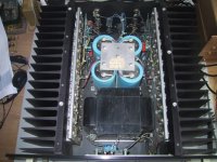
I repeat the attachment of the following old photo, which has been already in another thread. With this photo, the thing I'd like to indicate is that I really like the sound of F4 and Babo Zen as I have mentioned in that thread as follows:
"If I compare F4 with Babo Zen, Babo zen gives me a bit heavier punch while F4 controls the bottom end somewhat better. I don't know whether the difference is due to different preamps . . . ? Anyhow, I'm satisfied with both. "
"
and
"Papa,
¡¦
I promise that I will never give up both "Zen5 with Input JFETs" (Babo Zen) and "F4""
Uh . . . ? So, what?
Why about these amps, not F5 . . . ?
I open this thread to show new-building of my F5, and get both positive global and negative local feedbacks from you--technical things or whatever--and share any opinion.
I repeat the attachment of the following old photo, which has been already in another thread. With this photo, the thing I'd like to indicate is that I really like the sound of F4 and Babo Zen as I have mentioned in that thread as follows:
"If I compare F4 with Babo Zen, Babo zen gives me a bit heavier punch while F4 controls the bottom end somewhat better. I don't know whether the difference is due to different preamps . . . ? Anyhow, I'm satisfied with both.
" and
"Papa,
¡¦
I promise that I will never give up both "Zen5 with Input JFETs" (Babo Zen) and "F4"
" Uh . . . ? So, what?
Why about these amps, not F5 . . .
?Attachments
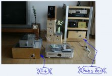
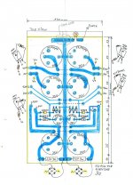
You see both my BaboZen and F5 . . . ? There is a major difference between BaboZen and F5 in the style of global negative feedback arrangement.
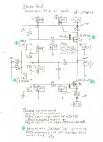
And, my F5 has minor diffrent resistor values, etc, compared with the original, as follows:
Long list and boring, isn't it?
>><<
And, my F5 has minor diffrent resistor values, etc, compared with the original, as follows:
- R3, R4, R15 and R16 will be changed from 2.2K to 2.4K because I have 2.4K instead of 2.2K in the drawer.
- TH1 and TH2 will be changed from 4.7K to 5K in consideration of availability.
- P1 and P2 will be reduced from 5K down to 2K. When I have 2K instead of 5K, the resistance-change/turning will be slower with 2K and it might provide me with a bit easier adjustment. And, P1 of 2K in cooperation with R3, R15 and TH1 will give me max. resistance of 950 between the +rail and the drain of Q1 so that the resistance is still enough for me to get the bias current. Of course, P2 will do the same for the lower half part.
- R5, R6, R7 and R8 will be 2w-grade, not 3W. I hope there will be no harm due to the heat.
- R19 and R20 will be changed from 150 to 160 ohms. Again, I find only 160 ohms in the drawer. This will reduce the maximum peak current from 10A down to 9.2A. For me, 9.2A is more than enough.
- As Papa recommends, I will increase R21 and R22. Not to 22K, but to 18K as I have only 18K . . .
Long list and boring, isn't it?
>>
<<Attachments
Sure, JJ. We could sacrifice all of (TH1/2, R15/16, Q5/6 and R17/18/19/20/21/22). A bravery!
For the new-building of my F5, I would like to use my old stuff as much as possible. The transfomer is not an exception. And, if it has secondary voltage of 2 x 18VAC, it would be pefect for me to get the rail voltages of 22-25V with simple standard CRC filter.
Papa didn't say that 22-25V rails give us the best result?
Unfortunately, my old EI transformer (500VA) has secondary voltages of 2 x 25VAC . . . If I use the simple CRC filter, I would get the rail voltages of 30-35V . . .
>> . . . . .
  . . . . .
  <<
<<
Okay, I will apply the souce follower voltage regulator and cut off upper part of the rail voltages so that I could have the rails of about 23V.
>><<
For the new-building of my F5, I would like to use my old stuff as much as possible. The transfomer is not an exception. And, if it has secondary voltage of 2 x 18VAC, it would be pefect for me to get the rail voltages of 22-25V with simple standard CRC filter.
Papa didn't say that 22-25V rails give us the best result?
Unfortunately, my old EI transformer (500VA) has secondary voltages of 2 x 25VAC . . . If I use the simple CRC filter, I would get the rail voltages of 30-35V . . .
>>
. . . . . . . . . . <<Okay, I will apply the souce follower voltage regulator and cut off upper part of the rail voltages so that I could have the rails of about 23V.
>>
<<Attachments

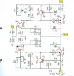
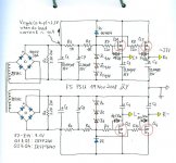
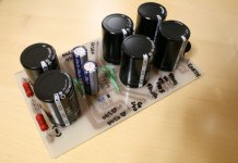
This is the power supply unit showing the source follower voltage regulators.
I'm using only one fltering cap of 33,000uF/35V behind the bridge. In this case, when I have the dc load current of 10A, I will see the ripple voltage of about 2.5V peak-to-peak just behind the filtering cap. The regulator would swallow up this amount of ripple, without any special effort.
Z1, Z2 and Z3 will provide the zener reference voltage of 27V. Then, I can get the rail voltage of about 23V. The large C7 is to eliminate the ripple current on the zeners (as internal resistance of the zener is not zero), and at the same time, to provide soft start to the amp.
R3, R4, R5 and R6 are to provide zener current of about 4mA.
D1/2 and Z7-Z14 are to protect the power Mosfets with respect to the max Vgs rating of 20V.
C3, C4, C5 and C6 are to squash the modulation at AC as Q1-Q4 are operated without feedback, and each of them has the output resistance of about 0.25 ohms. For details about this, please read The Zen Variations Part 5.
>><<
I'm using only one fltering cap of 33,000uF/35V behind the bridge. In this case, when I have the dc load current of 10A, I will see the ripple voltage of about 2.5V peak-to-peak just behind the filtering cap. The regulator would swallow up this amount of ripple, without any special effort.
Z1, Z2 and Z3 will provide the zener reference voltage of 27V. Then, I can get the rail voltage of about 23V. The large C7 is to eliminate the ripple current on the zeners (as internal resistance of the zener is not zero), and at the same time, to provide soft start to the amp.
R3, R4, R5 and R6 are to provide zener current of about 4mA.
D1/2 and Z7-Z14 are to protect the power Mosfets with respect to the max Vgs rating of 20V.
C3, C4, C5 and C6 are to squash the modulation at AC as Q1-Q4 are operated without feedback, and each of them has the output resistance of about 0.25 ohms. For details about this, please read The Zen Variations Part 5.
>>
<<Attachments
Babowana said:Sure, JJ. We could sacrifice all of (TH1/2, R15/16, Q5/6 and R17/18/19/20/21/22). A bravery!
For the new-building of my F5, I would like to use my old stuff as much as possible. The transfomer is not an exception. And, if it has secondary voltage of 2 x 18VAC, it would be pefect for me to get the rail voltages of 22-25V with simple standard CRC filter.
Papa didn't say that 22-25V rails give us the best result?
Unfortunately, my old EI transformer (500VA) has secondary voltages of 2 x 25VAC . . . If I use the simple CRC filter, I would get the rail voltages of 30-35V . . .
>>
Okay, I will apply the souce follower voltage regulator and cut off upper part of the rail voltages so that I could have the rails of about 23V.
>>
Beautiful piece of hardware
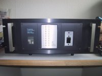
There is something special about a big hunk of a EI-trafo. Reminds me of the good old Threshold's Your choice of using a regulator is a good one. The regulator dispose off a lot of ripple/noise and there is a lot to be said for putting that beauty of a EI-trafo to work
This is what an old Stasis 2 looks like
Attachments

Sure, that was one of papa's better baby's Back then, you would have a hard time finding anything as good as the Stasis-amps This particular model was made around 1980.
Another OT picture (last one promise, but the beauty justifies it)
Talk about coolness factor
Back then, you would have a hard time finding anything as good as the Stasis-amps This particular model was made around 1980.Another OT picture (last one promise, but the beauty justifies it)
Talk about coolness factor
Attachments
 Beautiful ~
  <<
<<Babowana said:I am watching Boston Legal.
Candice Bergen . . . ?
Is she the same Candice Bergen on Soldier Blue?
My my . . .
>>
same one
- Status
- This old topic is closed. If you want to reopen this topic, contact a moderator using the "Report Post" button.
- Home
- Amplifiers
- Pass Labs
- New-building of my F5