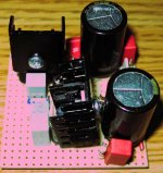
The image below shows a dual 5-VDC "mini" PSU circuit that uses LM340T-5 regs. The PSU was "designed" for a minimal-footprint layout (compactness) and, unfortunately, I did not take into account heat dissipation. One of the regs is used to power a 5V / 200mA digital decoder IC -- that's 1W of power draw. Additionally, my transformer outputs about 11.7VAC with load (I don't have anything smaller; the post-rectifier voltage, i.e., at the input of the reg., is 9.2VDC), so regs have to dissipate the "extra" voltage. Any hints on transformer sizing for this reg. is appreciated. My input AC is 116-117VAC.
Not sure if you can discern in the image, but I'm using two "stacked" heat sinks per regulator. Even then, the reg that powers the 200ma IC gets too hot to touch after about 15min. I don't have much room to stack more sinks (mostly because the sinks are pre-sized). I could rig some ad hoc sinks out of Al foil, Cu foil or other material -- any suggestions?
The main worry -- thx to thermodynamics! -- is that the nearby electro caps are "absorbing" some of this heat. I.e., they feel warm after the PSU has been running for about 20-30min, especially the aluminum part on top. Is there some way to "blanket" or insulate these caps?
This is just a proto-board ckt and the final version will be on PCB with better layout. But that won't be a reality for another two mos., so I need an interim solution. I don't want to re-layout on the proto-board because it does not have much room as is.
Thx!
Attachments
hollowman said:Additionally, my transformer outputs about 11.7VAC with load (I don't have anything smaller; the post-rectifier voltage, i.e., at the input of the reg., is 9.2VDC), so regs have to dissipate the "extra" voltage.
 (11.7 X 1.414) - 0.7 = 15.8VDC
 You're certain you only have 9.2VDC at the input of the reg ? Because you cannot have at the same time 11.7VAC loaded at the output of the xformer and 9.2VDC at the input of the reg.
Or are you using a CRC filter ?
Re: Re: Controlling regulator heat via sinking/shielding
I'm using an Amveco 62034 xformer. It's wired for 230VAC config. -- for a native 115VAC line voltage -- so I can use the whole xformer (parallel) for 9VAC output (I do this 'cause I need all this xformer's current capacity).
Yes: 11.7VAC is the loaded voltage I measure on the secondary xformer outputs. The input of the reg is bypassed w/a 0.1uF film cap. I also have a std. 20mA LED at the input of reg. (parallel to the bypass cap), so I assume that drops 2-3VDC.
00940 said:
You're certain you only have 9.2VDC at the input of the reg ? Because you cannot have at the same time 11.7VAC loaded at the output of the xformer and 9.2VDC at the input of the reg.
Or are you using a CRC filter ?
I'm using an Amveco 62034 xformer. It's wired for 230VAC config. -- for a native 115VAC line voltage -- so I can use the whole xformer (parallel) for 9VAC output (I do this 'cause I need all this xformer's current capacity).
Yes: 11.7VAC is the loaded voltage I measure on the secondary xformer outputs. The input of the reg is bypassed w/a 0.1uF film cap. I also have a std. 20mA LED at the input of reg. (parallel to the bypass cap), so I assume that drops 2-3VDC.
I'm using an Amveco 62034 xformer. It's wired for 230VAC config. -- for a native 115VAC line voltage -- so I can use the whole xformer (parallel) for 9VAC output (I do this 'cause I need all this xformer's current capacity).
Got a schematic?
If you have a good idea of the amount of heat you want to burn off use a resistor ahead of the regulator -- less work (and less heat) for the regulator to deal with.
You can also use a smaller regulator with an outboard pass transistor -- if you are drawing a lot of current you might want to use one of the Darlington's.
You can also use a smaller regulator with an outboard pass transistor -- if you are drawing a lot of current you might want to use one of the Darlington's.
No schematic -- nothing special here, folksDigitalJunkie said:Got a schematic?
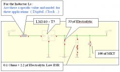
Pretty std. 4-diode rect. w/1000uF main cap + 0.1uF bypass. (The trans leads have 100R+0.1uF snubber, too.)
After the rect., see schema below (but disregard the 12VDC input).
Attachments
I don't have a good ideajackinnj said:If you have a good idea of the amount of heat you want to burn off use a resistor ahead of the regulator -- less work (and less heat) for the regulator to deal with.
Given that my application requires 5VDC and 200mA, what do you suggest?Thx!
I believe that the LM340T has dropout voltage of 2V, if you assume a line voltage swing of +/-15% the minimum you should be getting from the 9V winding is about 11.7 * 85% = 9.9V (probably during a brownout or something like that). So you need to drop a bit less than 2.9 V. Let's use 2V and allow the reg to do some work. 2V/0.2A = 10 ohms, at least 1 Watt (and preferably 2).
The regulator itself is a little piggy, drawing 6mA quiescent current.
You don't have to be overly fussy with the capacitors on the output side of these early regulators, it's the low dropout variety where the capacitor is an important part of the compensation.
The regulator itself is a little piggy, drawing 6mA quiescent current.
You don't have to be overly fussy with the capacitors on the output side of these early regulators, it's the low dropout variety where the capacitor is an important part of the compensation.
5V regulated supply needs 6Vac to 7Vac transformer.
For regulated 9Vdc to 18Vdc use a tranformer with the same AC voltage as the final regulated DC voltage
From 20Vdc and upwards the AC voltage can be slightly lower than the required regulated DC voltage. 25Vac for a 26Vdc to 27Vdc supply.
For regulated 9Vdc to 18Vdc use a tranformer with the same AC voltage as the final regulated DC voltage
From 20Vdc and upwards the AC voltage can be slightly lower than the required regulated DC voltage. 25Vac for a 26Vdc to 27Vdc supply.
Thx for that info. Earlier you noted: "If you have a good idea of the amount of heat you want to burn off use a resistor ahead of the regulator ..." By "ahead" do you mean: before the reg and in series with the input, or after the reg?jackinnj said:I believe that the LM340T has dropout voltage of 2V, if you assume a line voltage swing of +/-15% the minimum you should be getting from the 9V winding is about 11.7 * 85% = 9.9V (probably during a brownout or something like that). So you need to drop a bit less than 2.9 V. Let's use 2V and allow the reg to do some work. 2V/0.2A = 10 ohms, at least 1 Watt (and preferably 2).
FYI, the datasheet for the LM340 notes that Vin has to be between 7.5 and 20vdc. I can get away with a 7VAC out xformer w/no issues, but a 5VAC xformer is not kosher.
that's why post9 says 6Vac to 7Vac.hollowman said:but a 5VAC xformer is not kosher.
hollowman said:Thx for that info. Earlier you noted: "If you have a good idea of the amount of heat you want to burn off use a resistor ahead of the regulator ..." By "ahead" do you mean: before the reg and in series with the input, or after the reg?
The 10R/2W resistor must be before the reg.
This being said. If you have really 9.2VDC before the reg (which, on second thought, is quite possible on average with 11.7VAC p2p and only 1000uF), you're only dissipating around 0.84W. There are plenty of small heatsinks with about 18°C/W that would fit on your board. Assuming an ambiant at 30°C, you're still under 50°, which is quite ok. "Stacking" the heatsinks won't help much, you have to find a taller one.
I'm just saying that because a 10R resistor drops your voltage a tad too much. I would use a 5R/1W + taller heatsink.
Effective!
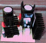
As far as the heat sinks, I used double-sided thermal tape to add more sinks (see below).
I only had 5R/3W resistors on hand, so I installed one in series betw. rectifier and Vin(reg). This worked well: the reg now runs only mildly warm.00940 said:The 10R/2W resistor must be before the reg.
This being said. If you have really 9.2VDC before the reg you're only dissipating around 0.84W. There are plenty of small heatsinks with about 18°C/W that would fit on your board. Assuming an ambiant at 30°C, you're still under 50°, which is quite ok. "Stacking" the heatsinks won't help much, you have to find a taller one.
... because a 10R resistor drops your voltage a tad too much. I would use a 5R/1W + taller heatsink.
As far as the heat sinks, I used double-sided thermal tape to add more sinks (see below).
Attachments
Why aren't you using switching? like lm2576, for this load you would even need heatsink, doesn't care what wold be input voltage,... can you use something like that or not, or you need to use what you did?
Here is my
Here is my
Use a switching regulator like LM2574, 2575 or 2576 and forget about heat problems. Input may be as high as 20V or 30V without much performance degradation. They can work with as little as 4 external components.
I would even recommend an off-line SMPS but building one from scratch is way too complex and dangerous for most people. Recycling some 5V 200mA switchmode power adapter (or old mobile phone charger) may be an interesting option, though.
I would even recommend an off-line SMPS but building one from scratch is way too complex and dangerous for most people. Recycling some 5V 200mA switchmode power adapter (or old mobile phone charger) may be an interesting option, though.
you WOULD NOT need any heatsing, sry for typo... and yes some old wall adaper would be even betterluka said:you would even need heatsink
Smps
SMPS are, soundwise and IMO, better-performing than what a lot of so-called audiophiles give them credit for. E.g., certain okay-performing Toshiba CD/DVD players use them. But that said, and in my albeit limited and statistically-insignificant experience, none have yet matched the SQ of traditional shunt or linear PSUs.
Further, I don't see them frequently recommended in the DIY community or represented in the marketplace or incorporated in "serious" manufactured audio products compared to "std." types. E.g. in myriad DIY projects, kits or products-for-sale sites:
http://www.borbelyaudio.com/psshunt.asp
http://www.audiocom-uk.com/control/news/anmviewer.asp?a=158&z=15
http://sjostromaudio.com/_unsql/hifi/index.html
http://www.paulhynesdesign.com/
http://www.at-view.co.uk/alwsr.htm
http://www.gammaelectronics.com/power-supplies-and-regulators-audio-hi-fi-diy.html
...etc.
Bottom line: There's an overarching consensus -- statistically-significant -- that non-SMPS PSUs are still the way to go. This may one day change as technology evolves.
All that said, I do think the ideas SMPS promoters present -- as in posts above -- are interesting and worth noting WRT PC-based audio systems.
Switching amplifier and power supply technologies, together with digital audio processing, are one or two orders of magnitude more complex than older and more rudimentary linear technologies.
Most of the circuits themselves don't contain much more parts than linear ones, but understanding the inner working requires a much deeper understanding of electronics. Most audio designers don't have that understanding and they are either too old or too lazy to study electronics deep enough, not to mention the specific switching and DSP techniques.
They are stuck to the more straight solutions, the ones that require less brain at the expense of wasting more space, resources and heat.
If these technologies started to rule the market from one day to another, 90% of current audio designers would be completely incapable of learning them and would be out of business immediately. This explains everything.
- Status
- This old topic is closed. If you want to reopen this topic, contact a moderator using the "Report Post" button.
- Home
- Amplifiers
- Power Supplies
- Controlling regulator heat via sinking/shielding