I got the DDDAC MK2 board, http://www.dddac.de/files/dddac-usb-1543-dac32.pdf. It's a USB sound player card. I modified the analog side of this board, adding a directly coupled cathode follower. And also modified the Rbias and the load resistors on the DAC chip's output. More about that at http://pw2.netcom.com/~wa2ise/radios/tubedac.htm and scroll about 7/8 down that page to find section titled "Modifying a player that uses a TDA1543 DAC chip".
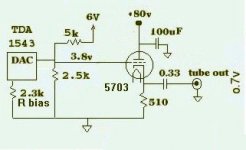
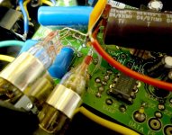
The DAC chip, the TDA1543, produces a constant DC bias voltage, which I used to bias the tube, a pair of 5703 submini tubes. A bias of 3.8VDC, and the cathode voltage and current is about 4V and 7.8ma. The tubes were wired direct to the DDDAC board, where the relay was designed to be. (Which means I never use the PCM2707's analog output). The cathode resistor is a 510 ohm surface mount resistor. If I did the cathode follower impedance calculation correctly, it would be about 140 ohms. Re=[(Ra/(u+1))*Rk]/[(Ra/(u+1))+Rk]. The 5703's Ra=5K, u= 26, Gm=5k. And u/Gm=Rp. (I also used surface mount resistors elsewhere on this board. Sure, you need a steady hand, but with 2 or 3 terminal devices, it ain't that bad. And I learned how to salvage SMD resistors and some caps off scrap boards, you need TWO soldering irons to heat both ends at the same time to desolder the part.). Anyway, I used the 5703 tube, as it has pretty good characteristics with low B+ voltages, like the 80V I was able to get from some spare switching power supplies I had. (Consisting of a 12.6V supply, to power the solid state stuff on the board, and atop that electrically I stacked a pair of 34V supplies to get approx 80V. I found the voltage regulating circuit in the 12V supply, and changed a resistor to make it produce 12.6V, which is what the tube heaters, in series, would want.).
Oh, and watch those wire leads on these sub-mini tubes. I busted one off one of the tubes, but I was able to chisel into the glass seal a little to get a short stub of wire to solder it back onto. (why not, nothing to lose at this point).
Attachments
and how does it sound compared to the original situation?
On the new DC bias you did, have you measured THD on a 0dB signal? I guess you will be surprised")
also, the fact you take the external 6Volt power supply in the signal path is not such a good idea. Not needed at all by the way. The 1543 will bias the Tube any way
take care
doede
On the new DC bias you did, have you measured THD on a 0dB signal? I guess you will be surprised
also, the fact you take the external 6Volt power supply in the signal path is not such a good idea. Not needed at all by the way. The 1543 will bias the Tube any way
take care
doede
dddac said:and how does it sound compared to the original situation?
On the new DC bias you did, have you measured THD on a 0dB signal? I guess you will be surprised
doede
I was going to use cooledit to capture the playing of a 1KHz tone, but I can't figure out how to get the stupid sound input jack on this laptop to work...

In any event, it sounds good to my ears (tube "warmth", aka a little bit of 2nd H). Simulations (Circuitmaker) suggest 2nd H 50dB down, and around 75 down 3rd and beyond. Be better if I could get an actual measurement, though. I could hook this machine with the DDDAC with tubes to another computer with a working sound card, but I won't have access to that for a while.
The TDA1543 should perform as one inside a CD player as it feeds the tube grids.
I assume you have not changed the 6 volt power supply on the dddac-board? In that case the bias of 3,8V is wrong and the Rload far too high. At 0dB you will have hard clipping signals. With low level music you wont hear this obviously....
The cathode follower function is working at its best when the voltage swing is relatively small versus the bias point. That is certainly not the case in this design. Normally you put the cathode at 1/2 VB (as rule of thumb)
I am not so sure you followed the right route here.
Question, why did you needed a cathode follower to start with? Are you driving long hifh capaciatnce cables? Or low impedance volume potentiometer?
Otherwise you have added more possible sources of problems that solutions
It would be better to do other tweaks, but lets start with what it is you were trying to solve?
dddac said:I assume you have not changed the 6 volt power supply on the dddac-board? In that case the bias of 3,8V is wrong and the Rload far too high. At 0dB you will have hard clipping signals. With low level music you wont hear this obviously....
The cathode follower function is working at its best when the voltage swing is relatively small versus the bias point. That is certainly not the case in this design. Normally you put the cathode at 1/2 VB (as rule of thumb)
I am not so sure you followed the right route here.
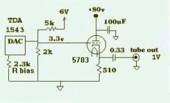
Good point on the 3.8V, I changed it to be at 3.3V by decreasing the old 2.5K to 2K. Which will also increase the loading.
The triode I used here I selected to be happy at the lowish B+ voltage, and the bias point. See
the 5703 at Frank's page 5. I'm drawing about 7ma plate current, at a B+ around 77V, with the grid about -0.4V compared to the cathode. Seems to be a linear spot.
Attachments
- Status
- This old topic is closed. If you want to reopen this topic, contact a moderator using the "Report Post" button.
- Home
- Amplifiers
- Tubes / Valves
- Modified USB DAC board, DDDAC with triode buffer