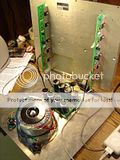
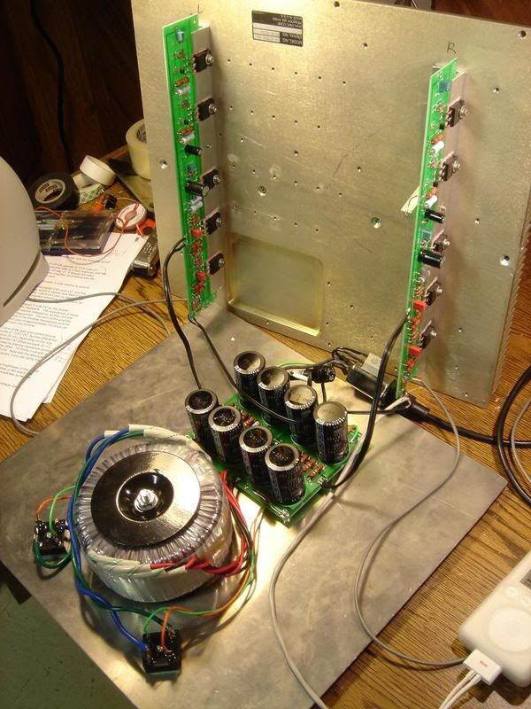
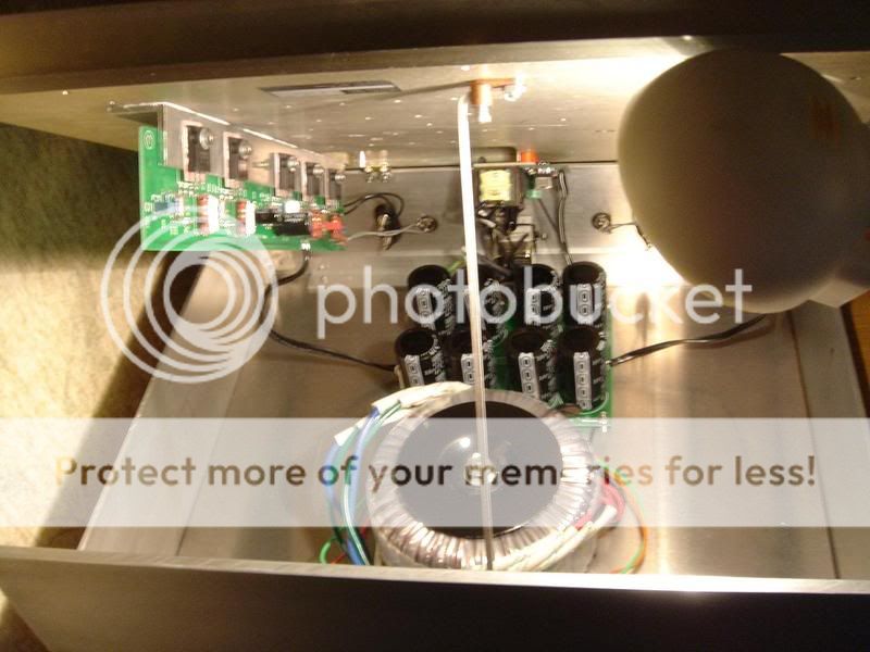
Yes, so after finishing off that Mini-A have been working now & then on a (somewhat) low-budget F1 clone build based on some PCBs suds offered.
Tonight fired it up, did measurements & all is fine with it (after that big, ugly 5 ohm 10 watt paralleled w/R27 got both channel offsets < 20 mV).
It's top will be all heatsink (hinges in the back so its 'hood' can be lifted). Also plan to use amb's nice ε24 pPower switch driver circuit & use rear-mount screws in the faceplace so that only the centered vandal-resistant/LED switch will show.
Another big thanks to Nelson for making it possible for this sort of thing to happen
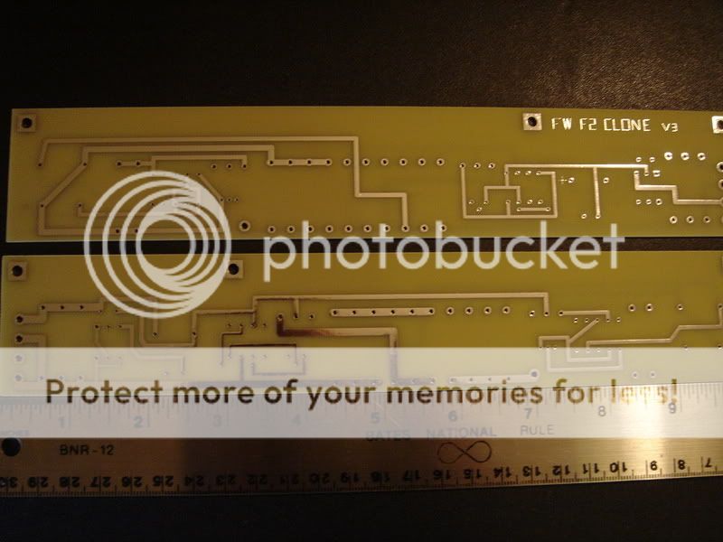
The fine print:There is the question of whether suds PCB offering meets the non-profit requirements for the use of the IP... At $100 USD for 2 full sets of boards shipped to US (total: 4 amp & 2 PS PCBs) covering alot of square inches & this single 2-set run/request, I'd think there is little or no profit. Just the small run based on PCB area would probably be several times that price from ExpressPCB for example. But by the looks of the marketplace thread, this offering didn't follow the traditional group buy way of things... There are a couple minor issues with the boards, like somewhat small traces, small pads & small holes... But no biggie for sure & silk screening is correct & matches the BOM I was able to construct.
Guess I'll post back after she's done (more alum shavings headed for the garage floor )
)
Tonight fired it up, did measurements & all is fine with it (after that big, ugly 5 ohm 10 watt paralleled w/R27 got both channel offsets < 20 mV).
It's top will be all heatsink (hinges in the back so its 'hood' can be lifted). Also plan to use amb's nice ε24 pPower switch driver circuit & use rear-mount screws in the faceplace so that only the centered vandal-resistant/LED switch will show.
Another big thanks to Nelson for making it possible for this sort of thing to happen
The fine print:There is the question of whether suds PCB offering meets the non-profit requirements for the use of the IP... At $100 USD for 2 full sets of boards shipped to US (total: 4 amp & 2 PS PCBs) covering alot of square inches & this single 2-set run/request, I'd think there is little or no profit. Just the small run based on PCB area would probably be several times that price from ExpressPCB for example. But by the looks of the marketplace thread, this offering didn't follow the traditional group buy way of things... There are a couple minor issues with the boards, like somewhat small traces, small pads & small holes... But no biggie for sure & silk screening is correct & matches the BOM I was able to construct.
Guess I'll post back after she's done (more alum shavings headed for the garage floor
)Nelson Pass said:The last small batch of boards I bought for First Watt ran me
about $1 per square inch.
Thanks for the info...
These amp boards are 2" x 12" each & PS boards are 4.6" x 5.5", so that's 48" sq for amp boards + 25" sq PS (about 73 sq inches per full set) & cost me $50 shipped (the 2 full sets were $100 shipped)...
I only priced out 1 pretty small "ProtoPro" board (double-sided, routed, silkscreened, modified someone else's F1 files ) @ ExpressPCB & the price was $180 + shipping for a single [oops - make that 4] 21 sq in (max) board
") [So I guess my "several times that" was a bit of an exaggeration]
[So I guess my "several times that" was a bit of an exaggeration] It appears the ship has sailed for DIY F1 builds, but my recently-purchased Hornshoppe horns are supposed to be a great match for the F1 (or visa-versa since I'm posting in this forum
Thanks again!
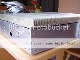
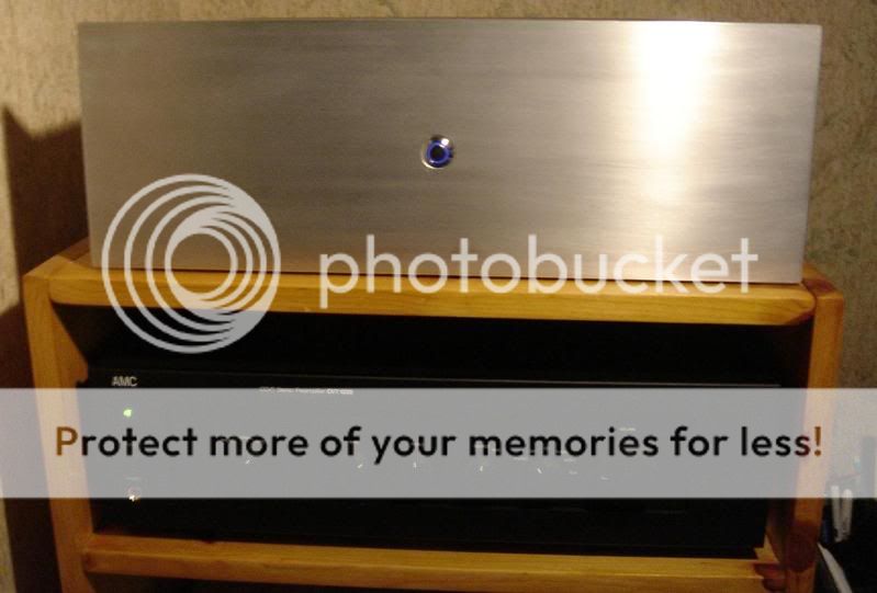
Almost there...
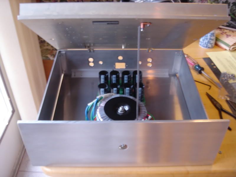
Lots of casework going on here... Final finishing is TBD & note metal & HS are scrap/surplus from ebay (think < $100 USD not incl shipping for HS & all plate).
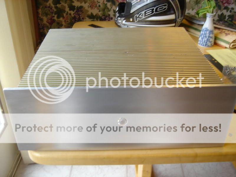
After a quick look around, I didn't find any other top-mount HS DIYs... But I think it may be the best thermally & there's no way I was putting any other components on top anyway.
Will be replacing that 16/17mm switch/LED w/a 22mm someday for sure
Need to remount amp boards & do some wiring...

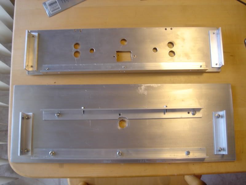
For this build, I'm (sortof) thermally isolating the HS by keeping a gap around it. A portion of HS from this side was used in my mini-A...
Front & back panels do all bracketing...
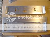
Learning again casework takes a lot of time... Esp. when your "machine shop" is an old table saw, $70 HF drill press, pad sander & dremel. BUT it's quite therapeutic for me as a break from the day job.
Lots of casework going on here... Final finishing is TBD & note metal & HS are scrap/surplus from ebay (think < $100 USD not incl shipping for HS & all plate).
After a quick look around, I didn't find any other top-mount HS DIYs... But I think it may be the best thermally & there's no way I was putting any other components on top anyway.
Will be replacing that 16/17mm switch/LED w/a 22mm someday for sure
Need to remount amp boards & do some wiring...
For this build, I'm (sortof) thermally isolating the HS by keeping a gap around it. A portion of HS from this side was used in my mini-A...

Front & back panels do all bracketing...
Learning again casework takes a lot of time... Esp. when your "machine shop" is an old table saw, $70 HF drill press, pad sander & dremel. BUT it's quite therapeutic for me as a break from the day job.
Re: Almost there...
That's really impressive metal work for those tools...
cfcubed said:Learning again casework takes a lot of time... Esp. when your "machine shop" is an old table saw, $70 HF drill press, pad sander & dremel.
That's really impressive metal work for those tools...
Re: Re: Almost there...
Thanks!
For me the casework took:
* Having built something prior (that Mini Aleph). Learn to account for panel overlaps, alum plate finishing, etc.
* Taps. I standardized on 6/32... If anyone noticed a shortage of them in central NJ you know who to blame That HS consumed 3 or 4 taps alone, but used an adjustable clutch cordless drill for most tapping. Ended up getting 10 taps for like $12 shipped off ebay.
* Time. Lots of measuring & re-measuring & test fitting, etc. But again, looked forward to working on it after the day job.
* 80-tooth non-ferrous blade & full cover-up when cutting (makes a plume of aluminum shavings & dust)
Plan to finish it up over the long weekend.
Nelson Pass said:
That's really impressive metal work for those tools...
Thanks!
For me the casework took:
* Having built something prior (that Mini Aleph). Learn to account for panel overlaps, alum plate finishing, etc.
* Taps. I standardized on 6/32... If anyone noticed a shortage of them in central NJ you know who to blame
That HS consumed 3 or 4 taps alone, but used an adjustable clutch cordless drill for most tapping. Ended up getting 10 taps for like $12 shipped off ebay.* Time. Lots of measuring & re-measuring & test fitting, etc. But again, looked forward to working on it after the day job.
* 80-tooth non-ferrous blade & full cover-up when cutting (makes a plume of aluminum shavings & dust)
Plan to finish it up over the long weekend.
Done
Finished her up last night... Looking & sounding good to me (chilled to Norah Jones)
Yeah, that $14 (ebay) LED switch has to go someday, need a bigger one & can't get it bright enough even from rail voltage. The $25 Bulgin is the way to go
That little bit hanging from the top in the back is that momentary switch / relay latch. Ordered the wrong transfo (220v) for me and had to scavenge one from an old wallwart.
WRT the recent unfortunate discovery that the PCBs I used violate the copyright of the orig boards guess that was an important side-effect of this thread (my higher-res photos).
I did do diligence to try assess legitimacy of the boards & Nelson let me know there's no ill will for me, but any future F1 DIYers should pursue other means of getting there while they patiently watch that space for NP's boards.
Learned a lot about a lot of things on this one!
Perhaps Suds will redo the artwork to make it original - I have no
issue with not-for-profit sales of DIY boards, but I do expect
people to respect material that is marked with a copyright.
The way the laws work, if I don't protect copyrights, patents, and
trademarks now, then I have a poor position to protect them in
the future.
issue with not-for-profit sales of DIY boards, but I do expect
people to respect material that is marked with a copyright.
The way the laws work, if I don't protect copyrights, patents, and
trademarks now, then I have a poor position to protect them in
the future.
Nelson Pass said:Perhaps Suds will redo the artwork to make it original <snip>
I decided there was room in this build for an additional personality, so I tried my hand at ExpressSCH & ExpressPCB:
Although it did take some hours getting the F2 schematic in (thanks yet again NP for sharing it!) & laying out the board, I found it another fun break from my daily grind...
Started by placing components in a similar arrangement to Nelson's boards, but as you can see, things did get a bit out of hand
There is certainly no mistaking this board for the original and keep in mind this is my 1st attempt at PCBs...Plan is to build these out & see about piggy-backing them on the F1 HS angle mounts & using another ε24 w/heafty 4PDT relays for each channel.
Nelson Pass said:The way the laws work, if I don't protect copyrights, patents, and
trademarks now, then I have a poor position to protect them in
the future.
That only makes sense & isn't sharing the schematics & even assisting people to build clones above & beyond anyway?
The above reminds me of a case a lawyer neighbor told me about where if someone makes it a habit to cut through your property & you do nothing to prevent it, you may find yourself not being able to interfere with the path.... IOW, the trespasser gains the right to the shortcut through your property...
Nelson Pass said:Another triumph for DIY.
Thanks! And it is looking like it will be a triumph... for me anyway
Only had one errant trace that needed cutting on my F2 boards (prevented P1 from balancing V+ (1/2 V+ at C3+)).
BTW, I was waffling between an F1 & F2 from the beginning after reading about them w/my horns & went initially for F1 because of PCB availability.
So, doing this because; of reading F1/F2 comps, cannot leave well enough alone, have the room in the case & adding F2 option would not be too expensive.
It's coming along nicely.. Here is the left channel F1/F2 bank installed & operational (note piggybacked aluminum Ls for each bank w/HS compound):
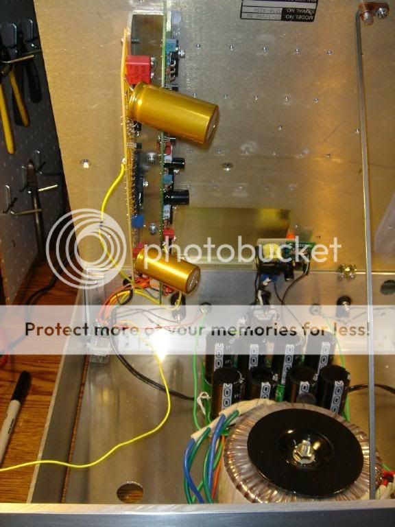
The left side F1/F2 package is working & sounding great even on my awful bench speakers. Expect both to sound great but different (e.g. like blonds vs brunettes, might want F1 bank in some situations & F2 in others). Although can be actively switched (mini DPDT switch on back swinging each PS rail ground to the relays), will be more of a day by day or week by week switcheroo I think.
F2 15kUF Caps - Yes, someday I'll pay attention to the SIZE column in my parts searches
but maybe bigger is better.$7 5A 4PDT single blank switch relay w/rail->12v reg:

Setup so that 12v REG (w/anti-noise caps) is connected to rail + & just waiting for PS ground/negative to come along.
No need for balanced input at this time, so switching V+, Out+, Out- & In+ (rest is shared).
Fun!
Whew, its done & working great.
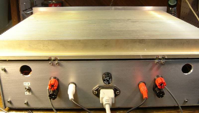
It's a wrap... NOW I think it'll stay closed for a while so I can listen to it Had to play with angle/location of those giant caps for open/close clearance...
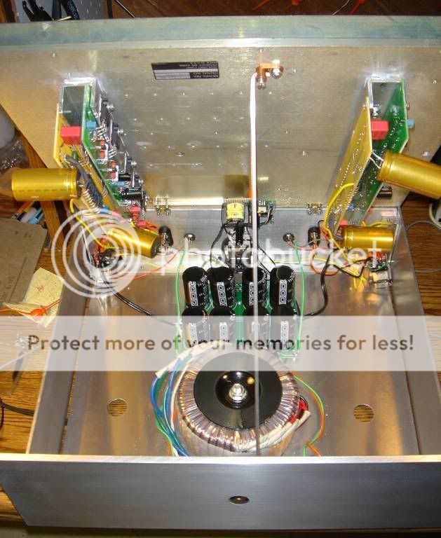
And although I may do the ε24 thing for F1/F2 bank switching someday (+ matching front panel switch), think the mini DPDT is fine:
back:
Think that's it for me for amps for a while - This thing is really the ticket for my setup...
Thanks again Nelson for releasing the designs into the wild.
P.S. I have experienced a couple ε24 dropouts in the couple weeks this has existed... Raised the ε24 470uf cap -> 1000uf but it could be that cheap 12v transformer OR 120v line transients.
It's a wrap... NOW I think it'll stay closed for a while so I can listen to it
Had to play with angle/location of those giant caps for open/close clearance...
And although I may do the ε24 thing for F1/F2 bank switching someday (+ matching front panel switch), think the mini DPDT is fine:
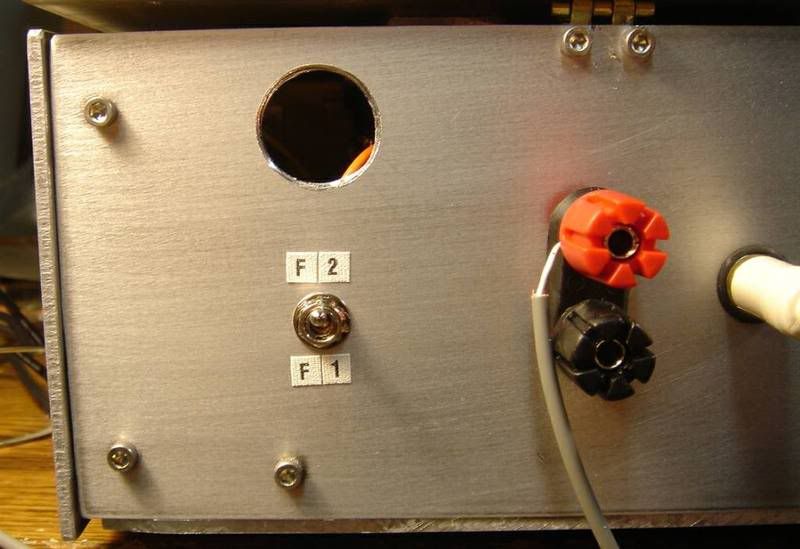
back:
Think that's it for me for amps for a while - This thing is really the ticket for my setup...
Thanks again Nelson for releasing the designs into the wild.
P.S. I have experienced a couple ε24 dropouts in the couple weeks this has existed... Raised the ε24 470uf cap -> 1000uf but it could be that cheap 12v transformer OR 120v line transients.
Neat

I like the switch piece,
do you just have the power ground tied to the switch between the two different amps PS inputs?
I assume the inputs and speakers outs are just all ganged together....
Can you get to full bias with heatsink the that. That's 200W of dissapation isn't it?
I like the switch piece,
do you just have the power ground tied to the switch between the two different amps PS inputs?
I assume the inputs and speakers outs are just all ganged together....
Can you get to full bias with heatsink the that. That's 200W of dissapation isn't it?
> do you just have the power ground tied to the switch between...
As I recall, I've got the power grounds tied & the input grounds tied (no balanced input)... So I'm switching input +, PS +, and both output leads (+ & -)... That's 4 poles per side.
It's running full bias, don't remember what F1s & F2s are dissipation wise, but again, only running one pair of channels at a time. And it works very well with that HS... It does not get hotter than about 50C AFAIR.
Congratulations on completing your build.
I have a couple general questions about the heat sinking ( I will be tackling an F5 in the near future).
How effective are the heat sinks with fins that are that shallow?
What is the compromise when attaching the output devices to angled aluminum and then having that attached to the heat sink. Is there a compromise or does the heat transfer still work adequately?
Good Luck.
WithTarragon said:
How effective are the heat sinks with fins that are that shallow?
What is the compromise when attaching the output devices to angled aluminum and then having that attached to the heat sink. Is there a compromise or does the heat transfer still work adequately?
Shallow fins - When building this & my miniA was scoping ebay for salvaged heatsinks. Think this one was 20"x14"x1.5" & I cut off 5 or 6" for the miniA. But top placement of the HS is best thermally I think... E.g. no fin surfaces are heating other fin surfaces, so can get by w/more shallow fins. I've no science to back this up tho.
L brackets - Finger testing seems to indicate the FETs are not that much hotter than L bracket & immediate HS area. Lapped the L bracket & mating HS section and used heatsink compound on surfaces.
Again, I believe I'm running "full bias", whatever that is
, and things are working quite well.WithTarragon said:Good Luck.
Thanks... I'll use the good luck wish for my current collaborative effort - nice little tube hybrid headamp since I'm good on speaker amps for a while
Re: 4PDT relays - I did recall correctly, from my post about them "Setup so that 12v REG (w/anti-noise caps) is connected to rail + & just waiting for PS ground/negative to come along. No need for balanced input at this time, so switching V+, Out+, Out- & In+ (rest is shared)."
Few more things about this build:
* Raised the ε24 470uf "tank" cap -> 4700 uF way back & get no dropouts from it now... The A/C circuit this amp is plugged into is heavily loaded, lights on it actually dim when sump pump or dehumidifier on the circuit kick in. So, not ε24's fault I had to raise this & I *should* move some things around A/C circuit-wise in the house.
* Heatsink - When I said I've no science to backup that top placement is thermally best, I should say other than the fact that heat rises
The heat spreads nicely across HS too, perhaps due to base thickness and the actual alum grade (hardness - did break 3/4 taps in it - far more than my other HS materials). Large, long L brackets help here too.
Thermally isolating HS from case should pay off too... Measured within-case temp and it peaks about 120degF (sides get warm - not hot). So its a nice comfy place for all the non-FET comps. Removing 1 screw allows me to raise HS & show it off too, using gloves on HS of course
Got some Elegant Anodized Alum feet that raise it up enough so bottom holes/case side slots feed air...
Wrong about "horizontal up" HS mounting attitude
Heh, talking to myself here again but need to clarify that, although this amp is working fine, it seems I was quite wrong about HS efficiency WRT top-mounting:
4.6. Thermal performance .v. mounting attitude
BTW upon rennovating the living room it appears this beast is not allowed to live there anymore. Marriage. Heh.
Anyway I'll be pulling the F1 boards & fitting them & a new PS in a smaller, remote-on-triggerable case to hide somewhere.
Originally posted by cfcubed After a quick look around, I didn't find any other top-mount HS DIYs... But I think it may be the best thermally & there's no way I was putting any other components on top anyway.
Heh, talking to myself here again but need to clarify that, although this amp is working fine, it seems I was quite wrong about HS efficiency WRT top-mounting:
4.6. Thermal performance .v. mounting attitude
BTW upon rennovating the living room it appears this beast is not allowed to live there anymore. Marriage. Heh.
Anyway I'll be pulling the F1 boards & fitting them & a new PS in a smaller, remote-on-triggerable case to hide somewhere.
PCB's
Hey cfcubed, I'm looking to build an F1 clone similar to yours but don't know where to go for the pcbs. Unfortunately I think a recent group buy fell through. It looks like at the moment the only option is to buy them in individual batches. If you (or anyone here) knows of a group buy or somewhere that will print them individually at a decent price, please help. Thank you.
Hey cfcubed, I'm looking to build an F1 clone similar to yours but don't know where to go for the pcbs. Unfortunately I think a recent group buy fell through. It looks like at the moment the only option is to buy them in individual batches. If you (or anyone here) knows of a group buy or somewhere that will print them individually at a decent price, please help. Thank you.
Re: PCB's
here are some pcb's
also here
jim
milezone said:Hey cfcubed, I'm looking to build an F1 clone similar to yours but don't know where to go for the pcbs. Unfortunately I think a recent group buy fell through. It looks like at the moment the only option is to buy them in individual batches. If you (or anyone here) knows of a group buy or somewhere that will print them individually at a decent price, please help. Thank you.
here are some pcb's
also here
jim
- Status
- This old topic is closed. If you want to reopen this topic, contact a moderator using the "Report Post" button.
- Home
- Amplifiers
- Pass Labs
- An F1 clone comes alive (better late than never:)