Hi i have followed peter daniels build instructions on the gainclone but I have finshed the amp boards but I am stuck on the bridge rectifier,
I want to use the amp in the stereo mode with one rectfier, do i solder on all 8 mur860 diodes and caps 50v 10uf and i would like to use the amp with out vol pot.
here is a link of the bridge rectfier
http://img297.imageshack.us/my.php?image=pict0011rectiferfd6.jpg
here is a link of both amps boards attached to heatsink.
http://img368.imageshack.us/my.php?image=chipampyk3.jpg
There are many different options for producing a power supply, but using the supplied diode bridge gives three main options when choosing a transformer.
A transformer with dual secondaries,
true center tapped secondaries
and two transformers with single secondaries.
The original standard application of this kit uses the first, a transformer with dual secondaries.
For this application, the primaries are attached to the mains,
while V+ and 0+ are attached to V+ and PG+
and V- and 0- are attached to V- and PG-.
Note that for a stereo amp,
one diode bridge can be used for both channels
or for monoblok applications, both bridges and two separate transformers can be used.
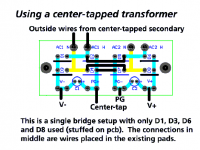
For the application of a true center tapped transformer, one with only three wires, V+, V- and 0, the following alternate arrangement can be used.
seems like you can use only one diode bridge = 4 diodes
for both channels = stereo
Attachments
DC Dave is right.
You should use all 8 diodes.
And use the instruction for dual secondaries transformer.
When we buy transformer we can get
2 x 22 VAC
2 x means it is two separate windings. Each on 22 VAC
Or we can buy/get
22-0-22 VAC
In this case is only one winding.
And in the middle of this winding is one connection to 0 Volt
I have been on peters daniels thread on the gainclone iwas making sure that i have everything wired up properly when i get my toriodal dont want a cap blown in my face. I noticed that certain people have used the 50v 10uf caps in rectifers and some have not which one should i choose for best performnace.
Joka22, those 10uf 50v caps are for the bridge rectifier.I was "experimenting" and I replaced those 10uf 50v caps with 10000uf per channel.and the bass got a lot stronger and tight.
Get some "alligator clips" and just try more capacitance per channel.that way it is easy to change and compare sound with different capacitors (capacitance).some people say the sound is faster with small caps(10uf 50v) but,I like the sound better with more capacitance 10000uf per channel.Good luck.
Get some "alligator clips" and just try more capacitance per channel.that way it is easy to change and compare sound with different capacitors (capacitance).some people say the sound is faster with small caps(10uf 50v) but,I like the sound better with more capacitance 10000uf per channel.Good luck.
joka22 said:I want to use the amp in the stereo mode with one rectfier, do i solder on all 8 mur860 diodes and caps 50v 10uf and i would like to use the amp with out vol pot.
If it says 2 x 22V on a transformer, chances are it's dual secondaries. In that case use one rectifier board with 8 diodes.
joka22 said:I noticed that certain people have used the 50v 10uf caps in rectifers and some have not which one should i choose for best performnace.
The small caps are optional, you can use them, but don't have to. It's best to evaluate both options and choose the one that sounds better
")
Small 50 Volt 10 uF capactitors.
I would use them!
It is good to have some caps right after diodes.
This improves filtering considerably. In my experience.
Even if the main electrolytic capacitors are on amplifier board.
It has nothing with sound to do. Even if some say so
It is only to give those LM3875 clean as possible power supply.
And so make the chip work as optimally as can be, electrically.
Evaluate chip amps by sound after some minute power supply detail changes
is nothing I would recommend.
Not even as a Blind ABX and more valid listening test.
Would not give any valid differences in sound. If anyone still like to think so.
But I guess Peter does not mind doing it in his more subjective way.
And who can stop him. Not me, for sure
Lineup - regards to old audio friend peter doing his great service for chip builders
Peter Daniel said:
The small caps are optional, you can use them, but don't have to.
I would use them!
It is good to have some caps right after diodes.
This improves filtering considerably. In my experience.
Even if the main electrolytic capacitors are on amplifier board.
It has nothing with sound to do. Even if some say so
It is only to give those LM3875 clean as possible power supply.
And so make the chip work as optimally as can be, electrically.
Evaluate chip amps by sound after some minute power supply detail changes
is nothing I would recommend.
Not even as a Blind ABX and more valid listening test.
Would not give any valid differences in sound. If anyone still like to think so.
But I guess Peter does not mind doing it in his more subjective way.
And who can stop him. Not me, for sure
Lineup - regards to old audio friend peter doing his great service for chip builders
10 uF or 6800 uF makes no difference
6800 uF is even better.
The important, in my opinion,
is that you use some electrolytic right after the rectifier diodes.
This will make a 2 capacitance filter: ( C-LR-C )
instead of only one electrolytic capacitor at mains pcb ( LR-C ).
LR stands for Inductance+Resistance of the wiring from the rectifier pcb.
okay i kinda half way understand that - what i have read on g.randy slone book is that caps help smooth the powersupply and smoother sound as the amp requests more power at high bass sounds so the caps help it by discharging the current to the amp without effecting the power supply. 50 watts per channel 6800uf is about right based on g randy slones thoery on caps for number of watts of per channel amps.
joka22
Could you lay your hands on some thickish alloy offcuts? You could mount the chip to an aluminium block to act as a spacer with thermal paste between it and the heatsink.
It would also put the heatsink between the chips and your transformer to give some screening, and keep the signal wires shorter.
John
- Status
- This old topic is closed. If you want to reopen this topic, contact a moderator using the "Report Post" button.
- Home
- Amplifiers
- Chip Amps
- my gainclone in build proccess need some help