I have choosen these drivers for my next project:
- Beyma SMC 2012/N (tweeter)
- Beyma PRO 6MI (mid)
- Subwoofer will be added later, for more info on my goals I refer to this thread:
http://www.diyaudio.com/forums/showthread.php?postid=1547534#post1547534
To design the crossover, I used SpeakerWorkshop. Unfortunately I couldn't find a "SpeakerWorkshop for Dummies", but this great walktrough provided what I needed:
http://bellsouthpwp.net/l/j/ljfrank/A_Speaker_Workshop_Tutorial.html#crossover
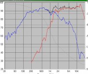
If you look at the attachment on the bottom, you'll see the result I have now.
The dip at 1000 Hz can be equalized out later I think - or choose bessel slope ??? there is a dip in the woofer responce so it is difficult to raise the responce thetr anyway IMO. Padding down the tweeter some more also shouldn't be a problem.
My questions are about the components SpeakerWorkshop proposed.
- Tweet: The acoustical slope is almost perfect to the 2nd order LR goal. SW seems to hint that I could do with only the cap, but as said/explained in the walktrough above, I'll keep the 2nd order electrical to protect the tweet.
- Woofer: The slope descends less than the 2nd Order LR goal, but since it will be listened to off-axis the high freq content will drop more and I think I shouldn't be too far from what I want. Am i correct about this?
SW says "422.2uH" so I think this is a 0,42 mH ?
Since I could do with only a cap on the tweeter, will the extra inductor provide enough protection?
Other ideas to improve?
- Beyma SMC 2012/N (tweeter)
- Beyma PRO 6MI (mid)
- Subwoofer will be added later, for more info on my goals I refer to this thread:
http://www.diyaudio.com/forums/showthread.php?postid=1547534#post1547534
To design the crossover, I used SpeakerWorkshop. Unfortunately I couldn't find a "SpeakerWorkshop for Dummies", but this great walktrough provided what I needed:
http://bellsouthpwp.net/l/j/ljfrank/A_Speaker_Workshop_Tutorial.html#crossover
If you look at the attachment on the bottom, you'll see the result I have now.
The dip at 1000 Hz can be equalized out later I think - or choose bessel slope ??? there is a dip in the woofer responce so it is difficult to raise the responce thetr anyway IMO. Padding down the tweeter some more also shouldn't be a problem.
My questions are about the components SpeakerWorkshop proposed.
- Tweet: The acoustical slope is almost perfect to the 2nd order LR goal. SW seems to hint that I could do with only the cap, but as said/explained in the walktrough above, I'll keep the 2nd order electrical to protect the tweet.
- Woofer: The slope descends less than the 2nd Order LR goal, but since it will be listened to off-axis the high freq content will drop more and I think I shouldn't be too far from what I want. Am i correct about this?
SW says "422.2uH" so I think this is a 0,42 mH ?
Since I could do with only a cap on the tweeter, will the extra inductor provide enough protection?
Other ideas to improve?
Attachments
And perhaps the .swd file could be of some help:
http://users.telenet.be/Hellhouse/public/TranceMachine2order.zip
(I put it here for the moment, as it is too big to attach in this reply.)
http://users.telenet.be/Hellhouse/public/TranceMachine2order.zip
(I put it here for the moment, as it is too big to attach in this reply.)
First thing I noticed is that you have a 1000 H inductor in your tweeter crossover. That's ridiculously big.  Even if you wanted 2nd order electrical you can't buy an inductor anywhere near that big.
Usually speaker workshop gives you 1000 H components after optimization if the component isn't needed or if the values your components started with led to a solution that didn't converge. In the latter case, you can change the values back down to something reasonable and optimize again to see if it will give you a more reasonable result.
The thing is you'll also be listening to your tweeter off axis which changes things a lot too.
What were the goals you set for your HP and LP?
Even if you wanted 2nd order electrical you can't buy an inductor anywhere near that big.Usually speaker workshop gives you 1000 H components after optimization if the component isn't needed or if the values your components started with led to a solution that didn't converge. In the latter case, you can change the values back down to something reasonable and optimize again to see if it will give you a more reasonable result.
The slope descends less than the 2nd Order LR goal, but since it will be listened to off-axis the high freq content will drop more and I think I shouldn't be too far from what I want. Am i correct about this? SW says "422.2uH" so I think this is a 0,42 mH ?
The thing is you'll also be listening to your tweeter off axis which changes things a lot too.
What were the goals you set for your HP and LP?
JLC7 said:First thing I noticed is that you have a 1000 H inductor in your tweeter crossover. That's ridiculously big.
One thousand henrys like in 1,000,000mH? Such a passive inductor made of copper wire would weigh several tons I imagine.
Cordraconis said:SW says "422.2uH" so I think this is a 0,42 mH ?
Yes
I'm no expert on SW, but I have figured out most of it to a first order anyway.
looking at your .swd, a couple of things:
1) no impedance information for the drivers? This is easy to measure with SW, a sound card, and minimal external components.
2) driver parameters for the tweeter are nonsense. The woofer looked more reasonable but still many of the values looked like a round value was just tossed in. This info can either come from the data sheet for the driver or via measurement with SW.
3) as others have pointed out, a 1000H inductor is clearly a nonsense result. If using the optimize feature gives either very large inductance values, or very small capacitance (pF) values, then you can delete the component. Make a change, re-calculate the response, then use ctl-Z / ctl-Y (undo / redo) to see the change.
I found that 4th order acoustic response could be closely approximated with a 2nd order network.
also see this website for a helpful tutorial:
http://www.claudionegro.com/
the learning curve with SW is tough but once you figure it out it is very powerful, frankly amazing for free SW.
Thanks for the replies guys! A few things:
@JLC7:
Yes, I couldn't find such a large coil in the online shop, and the largest they had was a ridiculously 125€ (+-200$) so I already concluded something wasn't right. When I said I would follow the explanation in the walktrough, I meant indeed changing to a lower value and reoptimized. Sorry if it wasn't clear and if I didn't upload the newer version.
Also I will be listening to the tweets on-axis as I'll mount them lying *on* the dashboard and not flush mounted (where they would have to reflect via the windshield.)
The goals were 2nd order L.R. for both, but after I created this thread I played around further and found out - like mightydub - that I could do a 4th order L.R. and still have the 2nd order electrical filter to protect the tweeter, so I'll change it to 4th order L.R.
What do you mean with the phase information? The SPL plot? I got the SPL plot and the impendance plot for the datasheets which I did an SPLTrace on.
The offset will be 0 after the addition of digital delays (much) later, so for now this shouldn't be an issue in the design of the passive crossover, unless I can be convinced otherwise?
@mightydub:
Strange, I did the SPLTrace of the impendance plot but in SW I don't see anything. Didn't notice that, thanks for bringing it up!
When I open the .zma file in SPL View I can see it so the data is there, however, the impendance rises slowly towards 4 Ohm at 20000Hz, while it should be around 16 Ohms in the plot I have here printed out next to me. Maybe something went wrong in the tracing or this is from the tweets T/S parameters I forgot to input in SW ...
Thanks for the link, but the site and the SW tutorial there seem to be orientated to doing measurements which is a bit hard one week prior to ordering the drivers and not having the equipment to measure.
My goal is to use the traces from the datasheet to make an as good as possible simulation of the passive crossover and to order the right caps and coils together with the drivers.
@willitwork: thanks for the reassurance. btw, for the current copper prices an inductor like that probably comes with its own sherpa to install it.")
I have to go now, but tomorrow I'll try to:
- Sanitize my inputs (i.e. re-do the impendance traces and input the T/S parameters and double check everything in SW!)
- change the desired slopes to 4th order L.R. and do the simulations/optimisations to get reasonable cap and ind values.
- upload everything, including the traces to the site for you all
- ask about what possible bumps I hit when trying to do the above.
If something is still not clear, feel free to ask me.
thanks again and hang on for more!
Joris
@JLC7:
Yes, I couldn't find such a large coil in the online shop, and the largest they had was a ridiculously 125€ (+-200$) so I already concluded something wasn't right. When I said I would follow the explanation in the walktrough, I meant indeed changing to a lower value and reoptimized. Sorry if it wasn't clear and if I didn't upload the newer version.
Also I will be listening to the tweets on-axis as I'll mount them lying *on* the dashboard and not flush mounted (where they would have to reflect via the windshield.)
The goals were 2nd order L.R. for both, but after I created this thread I played around further and found out - like mightydub - that I could do a 4th order L.R. and still have the 2nd order electrical filter to protect the tweeter, so I'll change it to 4th order L.R.
What do you mean with the phase information? The SPL plot? I got the SPL plot and the impendance plot for the datasheets which I did an SPLTrace on.
The offset will be 0 after the addition of digital delays (much) later, so for now this shouldn't be an issue in the design of the passive crossover, unless I can be convinced otherwise?
@mightydub:
Strange, I did the SPLTrace of the impendance plot but in SW I don't see anything. Didn't notice that, thanks for bringing it up!
When I open the .zma file in SPL View I can see it so the data is there, however, the impendance rises slowly towards 4 Ohm at 20000Hz, while it should be around 16 Ohms in the plot I have here printed out next to me. Maybe something went wrong in the tracing or this is from the tweets T/S parameters I forgot to input in SW ...
Thanks for the link, but the site and the SW tutorial there seem to be orientated to doing measurements which is a bit hard one week prior to ordering the drivers and not having the equipment to measure.
My goal is to use the traces from the datasheet to make an as good as possible simulation of the passive crossover and to order the right caps and coils together with the drivers.
@willitwork: thanks for the reassurance. btw, for the current copper prices an inductor like that probably comes with its own sherpa to install it.
I have to go now, but tomorrow I'll try to:
- Sanitize my inputs (i.e. re-do the impendance traces and input the T/S parameters and double check everything in SW!)
- change the desired slopes to 4th order L.R. and do the simulations/optimisations to get reasonable cap and ind values.
- upload everything, including the traces to the site for you all
- ask about what possible bumps I hit when trying to do the above.
If something is still not clear, feel free to ask me.
thanks again and hang on for more!
Joris
The SPLtrace data you got from the spec sheet is the response of the speaker in the manufacturer's specific test environment. This could be an infinite baffle, a box of set volume, etc. They usually tell you what it is. It's typically not exactly the actual response you get in real life. That will vary based on the box you build for the speaker and where it's placed.
So you run into a few problems. The frequency response data you have probably doesn't represent what the driver's response will be in the car. Any optimization you do with speaker workshop will be as much a shot in the dark as if you didn't have the manufacturer's spec data. It might be a good idea just using a stock crossover.
T/S parameters aren't necessary for SW to do crossover optimization. You typically use a few of the parameters to design a box, but that's it. SW just uses the frequency response, phase, and impedance to optimize the crossover.
Minimum phase data can be extracted from the frequency response data, but that data doesn't reflect what will happen in the car, so the phase data won't be valid either.
If you don't put the woofer in a suitable enclosure, it might not sound good. If you just mount the driver in the door it's anyone's guess what it might sound like.
Matching tweeter and woofer levels goes out the door because the tweeter will be on axis with your head and the woofer will be somewhere further away, mounted at an angle, and probably reflecting off of stuff.
Wow. I didn't realize car audio was so complicated. Maybe that's why some people don't bother. Even zaph mentions how he doesn't bother because the T/S parameters of the drivers changes with the temperature of the voice coil which in a car could range from extremely hot to extremely cold.
Sure you don't want to make a nice home hifi speaker?
So you run into a few problems. The frequency response data you have probably doesn't represent what the driver's response will be in the car. Any optimization you do with speaker workshop will be as much a shot in the dark as if you didn't have the manufacturer's spec data. It might be a good idea just using a stock crossover.
T/S parameters aren't necessary for SW to do crossover optimization. You typically use a few of the parameters to design a box, but that's it. SW just uses the frequency response, phase, and impedance to optimize the crossover.
Minimum phase data can be extracted from the frequency response data, but that data doesn't reflect what will happen in the car, so the phase data won't be valid either.
If you don't put the woofer in a suitable enclosure, it might not sound good. If you just mount the driver in the door it's anyone's guess what it might sound like.
Matching tweeter and woofer levels goes out the door because the tweeter will be on axis with your head and the woofer will be somewhere further away, mounted at an angle, and probably reflecting off of stuff.
Wow. I didn't realize car audio was so complicated.
Maybe that's why some people don't bother. Even zaph mentions how he doesn't bother because the T/S parameters of the drivers changes with the temperature of the voice coil which in a car could range from extremely hot to extremely cold.Sure you don't want to make a nice home hifi speaker?
OK, here is the problem: I've made the impendance traces again (*) but I just can't get them to display in Speaker Workshop. Changeing the amount of pionts, upper and lower freq limits etc ... it all doesn't help.
Maybe there is some program to convert it to a file format Speaker Workshop understands?
http://users.telenet.be/Hellhouse/public/TranceMachine/
Here are the data files and the .pdf where I got the traces from.
@JLC7: I'll answer tomorrow, but you can see some answers yourself in the PDF's.
*: I have to check the one from the PRO6MI, the scale seems off but the shape is ok.
look at the result you get from SPLtrace with a text editor (Notepad, etc.) - it should look something like this:
*created with SPLtrace
*Frequency Impedance
900.000 5.058
911.163 5.085
922.465 5.085
933.907 5.085
945.491 5.085
957.218 5.113
969.091 5.140
981.111 5.167
993.281 5.167
1005.601 5.195
1018.074 5.251
1030.702 5.279
1043.486 5.307
1056.429 5.336
1069.533 5.393
...
the * denotes a comment.
Frequency response will be similar except the right hand column will be dB instead of impedance.
Impedance files need to have a .zma file type, frequency response need to be .frd . Then right click on your driver, select Import, and select the type of file (.frd or .zma) and select the file.
I've spent the better part of the day re-downloading and re-installing SPL Tracer and Speakerworkshop since SPL Tracer supposedly doesn't work in windows XP? I've found no problems before but now I run it in win98 compatibility mode.
I opended the .FRD and .ZMA files in notepad and there are 3 columns of data in each one, the last column probably being the phase data as it is all zeroes. No problems there.
Maybe some good soul wants to run the FRC spreadsheet (I have OpenOffice and I couldn't get the macros to run, even with the security off) to generate the phase from the files on my homepage?
See my previous post for the URL.
On the website of the "walktrough" earlier in the thread I found a lot of .frd and .zma files which looked the same inside notepad as my traces. However, when I imported these into SW I could see the impendance curve! The only difference I could find with my files, is that my traces are way larger with more datapoints. I tried to trim them a few times and re-import them, but eventuelly I tried something else:
I simulated just the highpass filter of the tweet, but without the impendance data. I got an error message from SW that there was no valid impendance data, so I tried to manually set it to 8 ohm so SW would think the impendance curve was just a straight 8 ohm line.
It still wouldn't calculate the network.
Eventually I loaded the tweets .zma and it worked. After optimizing it, I switched the .zma from the tweet with that of the woofer and just recalculated it. The Spl curve looked different, so I came to the conclusion that SW *does* use my .zma files, but *if the dataset is too large it doesn't display the curve* when you import them.
I don't know if somebody can confirm that, but as far as I'm concerned it works now.
@JLC7: You'll see it is recorded in an infinite baffle, and the way I see it that means there is no rolloff/baffle step in the lower freq because the low sound waves cannot get around the baffle. In a closed car this holds true. Eventually if you go low enough, cabin gain will kick in and even reverse the rolloff, but this should be below this mid's resonance freq and a lot lower than the crossover point so I don't plan to concern with that. Further, if you go up in freq, the baffle matters less and less (unless it is so small it starts to diffract !!! which also shouldn't be an issue in car audio), up to the point where it starts to beam and even the woofers size is less an issue.
Feel free to correct me in this, but since the XO freq is high and a closed car resembles an infinite baffle enough at the mid-freq, I don't think it'll mess things up too much. I found a tutorial to substract the manufaturers enclosure responce, but what responce should I then add for a car?
The stock crossovers I saw were at different freq and only for the same Ohms for tweet and mid. Since I'll combine a Pro 8 Ohm tweet with a Car 4 Ohm mid, I have no option to do the crossover myself. At worst, it will be as good/bad as a stock, but looking at the parts count of some stocks, I think my 4th order LR will be better.
I'll put it in a separate enclosure inside the door, rather than just mount it into the (leaky! :wmash: ) panel. AkAbak or some other prog will quickly say how large the enclosure should be and then I'll see how much room there is. Since it's a mid, it won't be so big and franckly I think it is supposed to be smaller than ideal so the lower freq (200Hz and up) will rise some to be on par with the higher freq which are around 95dB/W/m ... I don't think they designed it with cabin gain starting from 500Hz in mind!
OK, then the matching can be done by ear once it is installed. I'll focus on getting a rather even responce then.
Car audio can be complicated if you try to do it Hifi-standallone-style, but I think if you make some good guesses about what's (im-possible and time-effective, you can get along fine.
Also, I do want to make some good hi-fi's later, but then I need to learn and test crossover design ...
thanks for the imput so far. More from me later, gotta go.
Well it's not exactly an infinite baffle. There are a lot of things for the sound waves to diffract off of and the space behind the door or wherever you mount the woofer will have an effect on its response too. That plus you're not listening to the woofer on axis. I know in some cars they're pointed at your feet... which makes a lot of sense. You know, because my legs enjoy hifi as much as my head does.
If I had to do a speaker system in my car, I'd probably start with a stock crossover and then tweak it until it sounded good to my ears. I think that will get you better results than trying to simulate the response of the speakers in an unknown environment. Just my opinion though.
If I had to do a speaker system in my car, I'd probably start with a stock crossover and then tweak it until it sounded good to my ears. I think that will get you better results than trying to simulate the response of the speakers in an unknown environment. Just my opinion though.
I think that you are setting yourself up for a great disappointment. Attempting to design by factory measurements in a well controlled room is hard enough, adding the complete inconsistency of a car interior complicates things even more.
If you are really interested in doing this well, you might look at investing a little bit in equipment. Claudio lists the necessary equipment at his site. He has done a great job of simplifying the walk through from measurement to design. For more detail, you can download the Unofficial Speaker Workshop Manual from his site (www.Claudionegro.com).
I recommend that you attempt to start a speaker system design with a home system. For auto, even with measurements, it is much more complex due to the variability of reflections and the ever changing environment (including temperature and exterior noise effects).
Not to be discouraging, but even with the best simulation packages, I think you will find quite a variance from real life with the situation that you are faced with.
Good Luck,
Jay
I hear you guys, and about 150$ worth of mic, preamp etc ... as measuring equipment is doable.
The thing is I'm listening to 4" fullrangers that probably came stock with the car which means the are at least 14 years (!) old and I think it is hard do do worse than that for the moment. Also, I have my hollidays within a few days and I must get the other (partial) sound system installed then or else it will take several months before I get another chance to immobilize/strip down my car ...
So I'll do it this way: I'll order the components and install the tweets and mids as good as possible with the XO in an accessible location for later adaptation. (much) Later I'll see for measuring equipement and measure everything installed in-car and tweak it then.
As you said it's very difficult to do it completely right in car audio, or else you just shouldn't bother which is what I'll end up with if my crossover design is completely borked, so no loss there, right?
I don't understand what you mean with a stock crossover. For me it is something like this:
http://www.hifisound.de/oxid/oxid.p...a5487d21.84396397/BEYMA-CROSSOVER-2-WAY-HIFI/
That doesn't exists for my drivers and tweaking it to-the-ear can as well (easier) be done with a self designed one.
If you meant a "textbook crossover" like the one you end up with this:
http://www.apicsllc.com/apics/Misc/filter2.html#fourth
then I still think the one from Speaker Workshop would be better?
I got the inputs right and I simulated the highpass and lowpass filters in SW to end up with an acoustical 4th order LR for both. This consists of a 3rd order electrical filter for the tweet and a 2nd order one for the mid.
I didn't use an L-pad for the tweet, as I noticed it effected the values of the caps and inductors in the cirquit (tweet resistance is modified by L-pad) and I'll change the gain on the amplifier so I won't use an L-pad either. This gave me the most accurate values.
Then I looked in the online shop which values were available and I put them manually in the SW cirquit. Each time I optimized the network (minus the component-value from the online shop) and choose the next component value untill I ran out of components to pick.
Simulation of the final network gave very negligable differences with the first optimized/suggested values.
http://users.telenet.be/Hellhouse/public/TranceMachine/TranceMachineComp.swd
There are some large values, but as far as I can see from the available ones from the shop, nothing outrageously expensive so i suspect no errors in the cirquit.
- Status
- This old topic is closed. If you want to reopen this topic, contact a moderator using the "Report Post" button.
- Home
- Loudspeakers
- Multi-Way
- Some SpeakerWorkshop crossover design q's