I've just assembled my LM3886t amplifier, based on the
schematic published in Elektor. When I switched the psu on
my first amp gives -vcc on the speaker out terminal and the
heatsink was hot, the second one finished his audio career
with pffffff sound, and a bit of smoke") , -vcc was on the
, -vcc was on the
output too. I checked everithing on the schematic, soldering,
components, psu and found no errors.
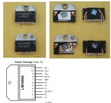
So I decided to disassemble the ic, I've simply cut out the ic
from the pcb, and what was found inside was a bit confusing for me
1. According to the lm3886 documentation from National pin 2,6 and 11
are NC , and I was just wodering why the guys from National put so thick copper wire on these pins ? (pin 6 is not visible on the cracked ic)
2. the die is at very "strange" angle, is it normal ?!
or is it just another fake , LM3886T, or in worst case another type
of ic in to220-11 case with (re)printed label ??
schematic published in Elektor. When I switched the psu on
my first amp gives -vcc on the speaker out terminal and the
heatsink was hot, the second one finished his audio career
with pffffff sound, and a bit of smoke
, -vcc was on theoutput too. I checked everithing on the schematic, soldering,
components, psu and found no errors.
So I decided to disassemble the ic, I've simply cut out the ic
from the pcb, and what was found inside was a bit confusing for me
1. According to the lm3886 documentation from National pin 2,6 and 11
are NC , and I was just wodering why the guys from National put so thick copper wire on these pins ? (pin 6 is not visible on the cracked ic)
2. the die is at very "strange" angle, is it normal ?!
or is it just another fake , LM3886T, or in worst case another type
of ic in to220-11 case with (re)printed label ??
Attachments
I have another experience
I have another experience.
I am running audio shop on internet. When I ordered PCM1704K to TI's branch. and I get them from the branch. When I tested pcm1704, vcc and gnd were shorted. I asked the reason to branch.
Then I got the answer that there were not stock so they bought in the Cxxxxx and gave them to me.
So I returned all pcm1704.
woooooo
Did you use a debugged pcb or was it some home-brewed solution? My guess is that you actually forgot something in your designthoronx said:I've just assembled my LM3886t amplifier, based on the
schematic published in Elektor. When I switched the psu on
my first amp gives -vcc on the speaker out terminal and the
heatsink was hot, the second one finished his audio career
with pffffff sound, and a bit of smoke
output too. I checked everithing on the schematic, soldering,
components, psu and found no errors.
So I decided to disassemble the ic, I've simply cut out the ic
from the pcb, and what was found inside was a bit confusing for me
1. According to the lm3886 documentation from National pin 2,6 and 11
are NC , and I was just wodering why the guys from National put so thick copper wire on these pins ? (pin 6 is not visible on the cracked ic)
2. the die is at very "strange" angle, is it normal ?!
or is it just another fake , LM3886T, or in worst case another type
of ic in to220-11 case with (re)printed label ??
Did you ever check the PS before you connected the LM3886. Did you have proper voltages? Where all pins conected where they sould? Did you check your power ground and signal ground?
NC pins are thick but this comes from the manufacturing. You'll understand this if you know how they package the chip.
The copper wires in such packages are usually made from a stamping out of sheet metal. In order to reduce cost, a universal stamping is used. Therefore, even if a pin is NC, the wiring may still be present in the package, because other IC types in the same package might need it.
I have no firm explanation for the strange die orientation, but it might just be to make some die connections accessible.
Did you verify your amp with a known good LM3886? Could you post a picture of your build?
I have no firm explanation for the strange die orientation, but it might just be to make some die connections accessible.
Did you verify your amp with a known good LM3886? Could you post a picture of your build?
Peranders is right, the LM3876 and LM3886 die are not rotated in the package. Also, there needs to be some clarification on NC pins. The lead frame will have pins running up to the DAP (die attach petal) but not wires from the die to the lead frame. If you actually see wires then it is not from National. Lead frames are some what generic. The 11 lead TO-220 package used for the LM3886 is exactly the same one used for the LM4700, LM2876, LM3876, and other parts at National. But the bond out will be specific for the part so a NC for these parts will absolutely not have wires. Some other ICs will but then should clarify in the datasheet if the NC is truly open or used in testing and should be left floating, isolated, or GND on the PCB. Although not clearly stated in the LM3886 datasheet about the NC pins I know that they are floating and you can do as you please with them without affecting the die.
-SL
-SL
Hi,
On the pictures posted, I can't see any bond wires, so there is no telling if they are actually connected or not. The lead fream doesn't look suspicious to me, but the die rotation might.
Faking is a real problem, not limited to the highest priced IC's per se. If re-labeling cheap devices as somewhat more expensive ones earns a few cents, then it's worthwhile for a faker to do it.
A little more searching yielded this thread:
Picture of a fake LM3886
Which adds more than a little bit of credibility to the "fake"hypothesis. Don't rule out circuit error though!
timpert said:
I can't get this to work.
Anyone else have problems ?
Andy
They may also be remarked. The LM4700 is rotated like that. The LM3886 & LM3876 should have double bond wires to the ouptut, Vcc and Vee pins. If single wire it is absolutely not a LM3886 or LM3876. The LM4700 also has a Standby pin so see if there are wires there. If you can get a scope you might be able to read the name on the die. This will tell you what it is but this can also be faked.
It would be quite a big mistake to assemble parts wrong. And these parts are tested after assembly unlike some super small ICs where test is limited to wafer form only. Possible National made an error but more likely there is something 'funny' with these parts.
-SL
It would be quite a big mistake to assemble parts wrong. And these parts are tested after assembly unlike some super small ICs where test is limited to wafer form only. Possible National made an error but more likely there is something 'funny' with these parts.
-SL
Last week I cracked a couple of LM3886T's and LM3886TF's, witch absolute can't be fake. Since then I had a new key-ring
It was exactly the same as yours, same die on an same "strange" angle. So I really think the chips are the "original" National ones.
Success with youre amp!
Robert
It was exactly the same as yours, same die on an same "strange" angle. So I really think the chips are the "original" National ones.
Success with youre amp!
Robert
Well maybe it changed some time but Robertj88 is right, the LM3886 is rotated just a little counter clockwise, just like your picture. The die ID should be at the bottom towards the right to look at if you have a microscope. So it is looking more like you do not have fakes, might want to spend time double checking circuit.
Sorry for the confusion earlier about rotation.
-SL
Sorry for the confusion earlier about rotation.
-SL
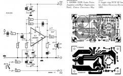
1. Psu
1. PSU (Suspected!)
The unregulated PSU was built based on carlosfm's psu design with small exception, I have used two rectifier bridges instead of one, the transformer is about 400VA, with center tapped secondary (3 wires), after I have assembled the psu, I mesured the voltages on the output without the amp connected,and without any load, it was nearly +-30V, far in the safe operation area of the LM3886.
- Status
- This old topic is closed. If you want to reopen this topic, contact a moderator using the "Report Post" button.
- Home
- More Vendors...
- Elektor
- Fake LM3886T ????