Hi all,
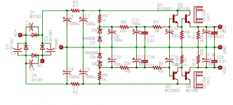
I want to try a new power supply for my new line stage, but i'm not sure if i have enough filtration in location C5, 6, 7 and 8. My new line stage is in this thread.
http://www.diyaudio.com/forums/showthread.php?s=&threadid=121745
thank you! Maxpou
I want to try a new power supply for my new line stage, but i'm not sure if i have enough filtration in location C5, 6, 7 and 8. My new line stage is in this thread.
http://www.diyaudio.com/forums/showthread.php?s=&threadid=121745
thank you! Maxpou
Attachments
maxpou said:sorry for my bad english, but i mean if i need more filtration or it's ok, because i found a 1000uF ROE EKO and i think it's a good capacitors? Thank you! Maxpou
I meant - it's enough with that amount of capacity you show on schematic ;
of course - more is always better
maxpou said:Hi Guys,
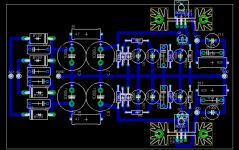
thank you for replys, this is my PCB. comment please? Maxpou
More copper !!!
Connect GND to a power plane that fills in all the unused copper.
It decreses the impedance of the tracks and also uses less etching chemicals.
A) the two AC inpouts should be farther apart to ensure easy soldering with no possibility of shorts. The AC "wires could be made larger (i.e. beefier).
B) The ground "wire" runs down the center. What would be ideal is for every component to have a wire directly to the common point of all grounds (star patern). However, the easy fix is to change this 'wire' into a solid layer filling all available space in the cernter with a couple of cutouts for the components that intrude on this 'bus'.
C) The V+ and V- "wires" should be beefed up similar to those of the ground system, but section at a time. For example, the wire connecting components around C6 should be approximately a parallelogram.
D) I, personally, would be tempted to gun the grounding point out and under the diodes and capacitors near the AC inputs such that the whole AC part of the system is isolated with a ground strap. Thus, the wire from point PGND is extended to the left and then splits and runs under the Ds and Cs at least to the edge (top/bottom) of the board. Thus isolating the AC section.
E) I would be tempted to rotate R3, R4 90 degrees and move r5, r6 to the right allowing the zerars to move outwards, simplifying the route in the mid section of the supply.
Hi,
Mitch's comment B must be adhered to or at least the dirty grounds from the smoothing end MUST have a separate route to the star ground AT THE OUTPUT.
I would recommend that the regulator ground also has a separate route. That makes 5 legs to the star on the PCB side and a further leg for the output side.
I think a ground star will perform better than a ground plane at keeping the dirty charging pulses out of the clean grounds that determine the output ripple.
jackinnj said:Shouldn't the 1N4148's be reversed?
Refering to schematic:
http://www.diyaudio.com/forums/attachment.php?s=&postid=1524207&stamp=1212103755
Yes, the 1N4004 (D7,D8) are put wrong way in figure.
jackinnj, you suppose 1N4148
Yes, I think, using signal (switch) diode 1N4148,
is a better choice here, than some ordinary rectifier diode, like 1N4004.
For higher current we can use 1N4448.
Both 1N4148 / 1N4448 should be safe to use upto ~ 100 mA.
1N4148 and 1N4448, max forward current:
150 mA
Foward Voltage drop, Vf
- 1N4148: ~ 1 V at 10 mA operation
- 1N4448: ~ 1 V at 100mA operation
lineup
Thank you guys for reply!
Hi lineup,
why? Maxpou
lineup said:
Yes, the 1N4004 (D7,D8) are put wrong way in figure.
lineup
Hi lineup,
why? Maxpou
maxpou said:Thank you guys for reply!
Hi lineup,
why? Maxpou
The diodes are wrong, the zeners wont work with the diodes tha tway around.
nigelwright7557 said:
The diodes are wrong, the zeners wont work with the diodes tha tway around.
Ok, if i reverse the diodes as jackinnj said to me.
Mooly said:Hi,
If your after low PSU noise have you considered a shunt reg rather series ?
Regards Karl
Yes, i considered a shunt reg, but i read this threads and i want try it for my lige stage. If somebody tell me shunt reg it's better for my application i will try a shunt later?
http://www.diyaudio.com/forums/showthread.php?postid=379305#post379305
http://www.diyaudio.com/forums/showthread.php?s=&threadid=33191&highlight=
Thank you! Maxpou
Hi,
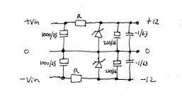
A shunt reg could be so simple on your amp boards, two zeners, one across each rail at the amp itself. You look to have all the decoupling you need at the amp itself. A series resistor to suit, say allowing 30 ma or so in each zener. You know the sort of thing. Beats having a reg off board, you might be suprised how good and noise free this is.
Think of it as a class A P.S.U.")
A shunt reg could be so simple on your amp boards, two zeners, one across each rail at the amp itself. You look to have all the decoupling you need at the amp itself. A series resistor to suit, say allowing 30 ma or so in each zener. You know the sort of thing. Beats having a reg off board, you might be suprised how good and noise free this is.
Think of it as a class A P.S.U.
Attachments
Hi,
The regs in your attachement just use a transistor to effectively create a high wattage zener. I would imagine your line amp will draw little current and so the zener on it's own is sufficient.
Out of interest what is the current draw ?
The simple arrangement I posted is essentially all I use in my Pre- Amp section--- it works really well, no noise on the rails--- if there are any transients on the unregulated supply the the shunt reg-- due to it's low dynamic impedance will suppress these much better.
Give it a try One zener and one resistor per rail per amp. Allow a small-say 20ma current to flow in the zener at all times, if you know the current draw of the amp and the unreg supply it's straightforward to caculate the resistor values.
Regards Karl
Edit-- And even better is to feed this from a "pre" regulator, this is actually what I did.
The regs in your attachement just use a transistor to effectively create a high wattage zener. I would imagine your line amp will draw little current and so the zener on it's own is sufficient.
Out of interest what is the current draw ?
The simple arrangement I posted is essentially all I use in my Pre- Amp section--- it works really well, no noise on the rails--- if there are any transients on the unregulated supply the the shunt reg-- due to it's low dynamic impedance will suppress these much better.
Give it a try
One zener and one resistor per rail per amp. Allow a small-say 20ma current to flow in the zener at all times, if you know the current draw of the amp and the unreg supply it's straightforward to caculate the resistor values.Regards Karl
Edit-- And even better is to feed this from a "pre" regulator, this is actually what I did.
- Status
- This old topic is closed. If you want to reopen this topic, contact a moderator using the "Report Post" button.
- Home
- Amplifiers
- Solid State
- Power Supply for jfet line Stage