Hi, It looks workable, Check C1/2 polarity, with it working, you show -300mv. I suspect this may vary either way depending on offsets. Q10 ? Is this in contact with heatsink/outputs for thermal compensation, how about a TO126 package here. Output inductor around 3 to 6 MicroHenry for stability ?
Regards Karl
Regards Karl
Hi,
I'm not sure about C7. Be cautious and test thoroughly.
I agree adding an inductor//resistor after the output Zobel. Try 1uH // 4r7.
Reduce C1 to 3u3F or 4u7F
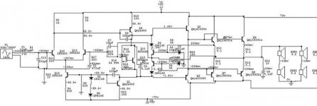
The gain is 101times (+40db). This is unusually high.
Increase R17 to a value from 470r to 1k0. Choose to suit the output of your preamp.
A 2pair output stage running on +-56Vdc should be OK with a load of 6ohms. But do ensure the heatsink stays cool for your duty.
The 0r1 emitter resistors need 15 to 25mV across them for all operating conditions. This will demand an output bias of around 200mA per output device and dissipate around 45W without any signal present. A big heatsink is needed just for this quiescent dissipation alone.
There are at least four resistors missing from the IV protection.
It has no transient pass ability. It will limit at the same current value irrespective of whether it is a very fast transient or a continuous DC output.
With protection fitted you will need to consider if the To126 VAS can survive a short to within 10Volts of the -ve supply rail during output current limiting.
The VAS and it's CCS will run warm due to nearly 340mW dissipation.
The CCS forces ~6mA through the VAS and this in turn unbalances the currents in the LTP halves. Change either the VAS current or the Collector loads on the LTP to ensure balance.
But how do you measure balance? Add emitter degeneration resistors to the LTP.
I'm not sure about C7. Be cautious and test thoroughly.
I agree adding an inductor//resistor after the output Zobel. Try 1uH // 4r7.
Reduce C1 to 3u3F or 4u7F
The gain is 101times (+40db). This is unusually high.
Increase R17 to a value from 470r to 1k0. Choose to suit the output of your preamp.
A 2pair output stage running on +-56Vdc should be OK with a load of 6ohms. But do ensure the heatsink stays cool for your duty.
The 0r1 emitter resistors need 15 to 25mV across them for all operating conditions. This will demand an output bias of around 200mA per output device and dissipate around 45W without any signal present. A big heatsink is needed just for this quiescent dissipation alone.
There are at least four resistors missing from the IV protection.
It has no transient pass ability. It will limit at the same current value irrespective of whether it is a very fast transient or a continuous DC output.
With protection fitted you will need to consider if the To126 VAS can survive a short to within 10Volts of the -ve supply rail during output current limiting.
The VAS and it's CCS will run warm due to nearly 340mW dissipation.
The CCS forces ~6mA through the VAS and this in turn unbalances the currents in the LTP halves. Change either the VAS current or the Collector loads on the LTP to ensure balance.
But how do you measure balance? Add emitter degeneration resistors to the LTP.
I totally agree with Andrew's statements.
Some more comment,
- I'd rather choose 0.22r emmiter resistors for the OP stage, with 10...15mV bias voltage across them (~50mA)
- C10 is low, try even 1nF
- Q1 needs base resistor when shared CCS is used for both LTP and VAS! Try 470r...1k
- R3 isn't needed, it's only adds more distortion
- C9 is not needed!
Anyway it's a nice conventional Lin-topology design. Your amp will work OK with the suggested modifications.
Calling Andrew!
What value are you preferring?
Some uses values for ~25...26mV drop, some for ~50...100mV, and some prefers even >100mV drop on them.
I'm courious about your preference related LTP degenerating resistors.
Add emitter degeneration resistors to the LTP.
What value are you preferring?
Some uses values for ~25...26mV drop, some for ~50...100mV, and some prefers even >100mV drop on them.
I'm courious about your preference related LTP degenerating resistors.
change the rails to 70 volts
There are at least four resistors missing from the IV protection where????
let make sure i understand the change
c1 and c2 reverse the polarity
change c1 to 3.3uF
remove r3 form the collector of q13
added a resistor to the bais for q1 470
changed r10 - r13 to 0.22
add inductor to the zobel end r24
There are at least four resistors missing from the IV protection where????
let make sure i understand the change
c1 and c2 reverse the polarity
change c1 to 3.3uF
remove r3 form the collector of q13
added a resistor to the bais for q1 470
changed r10 - r13 to 0.22
add inductor to the zobel end r24
Attachments
Hi Prorms, Well, it's like I said at the top, it's workable, it's how far do you want to go optimising it. I think 140volts a bit much to be honest, it's asking for trouble. The overload protection is as Andrew says, not complete, it works up to a point but is not ideal. I am sorry if it all sounds a bit negative ")
Where did you get the design from.
Where did you get the design from.
Hi Prorms, Do you understand how the protection part of the circuit works. You are putting a base-emmiter junction across the output resistors. When the voltage across R10 exceeds vbe the transistor will conduct and "short out" or reduce the drive to the drivers. The same happens on the "other half". All the other components do is modify this characteristic. R8/9 limit the base current to protect the transistors and together with R6/7 and the IN4148 form a non linear potential divider. You would also perhaps add a small delay network, a resistor and cap across R6/D3. This would give you the better transient response Andrew mentions. You can also further modify the base volts to the protection transistors by adding 2 further resistors to each "half", so that the supply voltage is also taken into account. This ensures the outputs are working within their SOAR or safe operating area at all times. Those 68 ohms look a bit low by the way.
Have you ever built any high powered gear like this before?
Karl
Have you ever built any high powered gear like this before?
Karl
prorms said:mooly
what would be a good wattage for q3 q4 q6 q7 max is 230
r4 is to keep the balance in q12 and q11 i change to 301
what would be a good value for 68 ohms ???/
add cap and a resistor across r6 and d3 what sizes ???
have you got your component numbering mixed up?
I'm lost!
Sorry, I dont follow you, Q6 is the voltage amplifier stage or VAS, Q11 is a limiter and Q12 is one half of the long tailed pair. Q12 and 13 would normally be thought of as being "in balance" but they never will be as it stands ( thats another mod, adding a current mirror ), but this in itself won't stop it working.
If you could rationalise the component ref's it would be easier to understand.
With the very greatest respect I think you will struggle to get a working amp out of this and in particular to fault find on it. The Zobel network is not correct, it just won't do anything as it is. The coil should be in series with the output, the cap and resistor to ground from from the output.
How were you intending to build this by the way, do you have a PCB ?
Regards Karl


- Status
- This old topic is closed. If you want to reopen this topic, contact a moderator using the "Report Post" button.
- Home
- Amplifiers
- Solid State
- is this poweramp ready to build????