Hey, I'm trying to work out how the bass pot of a baxandall tone circuit works. Atm I'm looking at the pot when it's turned fully to the right. That's the image I've attached to this post.
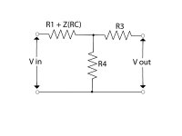
From some basic circuit electronics I know I can combine C1 & R2 to get Z(RC) = 1 / (s + 1/R2C1) but I'm a bit stuck then because you get three impedances 'looking' into the same node (I'll attach a drawing of this below) and that R3 really throws me off. If it wasn't there I'd know what to do but I'm really confused with it.
If anybody out there can offer me a helping hand then please do!
") Cheers, Jenks.
Cheers, Jenks.
From some basic circuit electronics I know I can combine C1 & R2 to get Z(RC) = 1 / (s + 1/R2C1) but I'm a bit stuck then because you get three impedances 'looking' into the same node (I'll attach a drawing of this below) and that R3 really throws me off. If it wasn't there I'd know what to do but I'm really confused with it.
If anybody out there can offer me a helping hand then please do!
Cheers, Jenks.Attachments
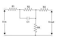
If the output is unloaded (high-Z) then R3 doesn't matter. In the passive Baxandall, R3 is only there to isolate the bass section from the treble section.
Here a nice article which deals with the details:
http://www.schmarder.com/radios/tech/tone.htm
- Klaus
Here a nice article which deals with the details:
http://www.schmarder.com/radios/tech/tone.htm
- Klaus
The transfer function you want to calculate doesn't take input/output impedances in account. So, if you imagine a source output impedance of 0 and an infinite input impedance, you can simply ignore R3, leading to:
Vout/Vin = R4 / (R4 + R1 + R2||ZC1)
If you know your input/output impedances, then ofcourse you can calculate everything (I assume?).
So, in most cases I assume Rin >> R3 and Rin >> R4. Then, effectively, R4 becomes R4||(R3 + Rin), leading to R4 again. If Rout << R1, then you can ignore that one also. Hope this helps...
.edit: too late
Cheers for that Klaus, however the circuit I'm using is a little different to that featured at the link you've included. I'm using the Baxandall circuit but with and op-amp incorporated and the circuit isn't grounded the same as it is in the link you provided either so I suspect the same rules don't apply.
I've attached a screenshot of my entire circuit. If you can help me out in trying to discover how the component values affect the frequency response of my input signal I'd really appreciate it.
Thanks.
I've attached a screenshot of my entire circuit. If you can help me out in trying to discover how the component values affect the frequency response of my input signal I'd really appreciate it.
Thanks.
Attachments
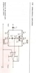
Look at the references given at the end. The spanish site (actually peru) deals with the opamp variant, which is indeed completely different.
Another nice way to figure out, especially if you're not into tedious math (well, who is?), is to use simulation. The free LTspice/SwCADIII (from linear.com) is quite fine, if not to say ideal for such tasks.
- Klaus
Another nice way to figure out, especially if you're not into tedious math (well, who is?), is to use simulation. The free LTspice/SwCADIII (from linear.com) is quite fine, if not to say ideal for such tasks.
- Klaus
You need a buffer ahead of it, otherwise it doesn't work as expected. Or a redesign with very high resistor/impedance values, but that's not really a good idea.jenks said:This circuit will be manipulating line level signal so does the input imedance match the value of the 4.7kohm (R3) resistor?
What then?
- Klaus
Limhes said:Just apply Kirchhof's and Ohm's laws for all resistors and impedances and you can work it out, knowing that the opamp's negative input terminal is at 0V...
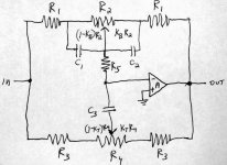
Here's the transfer function for the whole thing. I made a few changes in the designators. The two resistors on either side of the bass pot are R1. The bass pot itself is R2. The two resistors on either side of the treble pot are R3, and the treble pot is R4. The two bass capacitors are C1 and C2, with C1 being the furthest from the opamp. The capacitor in series with the treble pot wiper is C3 and the resistor in series with the bass pot wiper is R5. The opamp gain is assumed to be infinite (ideal opamp).
Attachments
jenks said:Hey there Electrician! That transfer function looks like a beast. How did you come up with it? I'm doing it in bits atm and it's taking ages with a pen and paper :-(
I did it with Mathematica. A person could probably use any of the other modern mathematical programs that can do symbolic algebra, such as Maple or possibly Matlab. I don't think it would be possible to get it right by hand!
I posted it somewhat as a joke. You can see how complicated it is, and I'm not sure that it's much help for understanding the circuit operation.
But, it is in fact correct, and if you substitute in the values for the various components and then plot it as a function of frequency, you get plots that are what you expect. You have to substitute 2*Pi*j*f for the Laplace variable s, and take the absolute value of the function (square root of the sum of the squares of the real and imaginary parts) for plotting.
One nice thing about using the full transfer function is that the effect of the bass components on the operation of the treble control, and vice versa, is correctly calculated.
One thing I did notice while doing some plots is that the R5 resistor (you called it R4 in your circuit in another thread; the one with the mid-band control) seems too low by at least an order of magnitude. As given, it limits the treble boost and cut to amounts much less than the corresponding bass boost and cut.
Sometimes I have found that if you substitute numbers for all the components but one, leaving that one symbolic, the transfer function simplifies enough to give some insight.
You can probably get more insight into the circuit operation by using a simulator and plotting families of response curves as you vary one component.
At any rate, you are right, the transfer function IS a beast. It's amazing how fast they get out of hand as soon as you have 4 or more nodes in your circuit.
Here's the schematic from which I got the transfer function.
I'll show plots of the gain with the treble and base pots going from flat to full up in increments of .1 for the coefficients Kb and Kt (fractional pot rotation) in subsequent posts. I don't know how to attach more than one image; maybe one of the moderators can tell me how to do this.
I'll show plots of the gain with the treble and base pots going from flat to full up in increments of .1 for the coefficients Kb and Kt (fractional pot rotation) in subsequent posts. I don't know how to attach more than one image; maybe one of the moderators can tell me how to do this.
Attachments
- Status
- This old topic is closed. If you want to reopen this topic, contact a moderator using the "Report Post" button.
- Home
- Amplifiers
- Solid State
- transfer function