I have a Knight KN928 integrated amp that I have used from time to time over the years. About ten years ago it was in use in my kitchen, when I noticed the output of one channel was getting
lower than the other. It did accumulate a lot of grease on the tubes in that environment, which I have since cleaned. It has
not been used much since then.
Now the output from both channels is VERY low. This unit uses 4 El84s in the output, 4 12ax7a in the preamp, and a 6CA4 rectifier.
I have swapped out all of these tubes with ones that I know to be good (well, they work in other units; I don't have a tube tester). The output level remains VERY low. This unit should put out at least 12 watts per channel, I'm sure it's nowhere near that now. When it was in my kitchen it drove smaller Advents easily.
I have little experience with working on tube amps, and have not woked on curcuits much since getting my EE 10 years ago.
However I have a lot of vintage tube gear and this one seems to be a relatively easy one to start with. I've read the FAQs on the dangers of working on tube gear.
Can anybody suggest where to start to look to troubleshoot?
Also I have been unable to find a schematic for this, anybody
have one they can share?
I can provide pics if that helps.
Thanks
Kirk
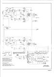
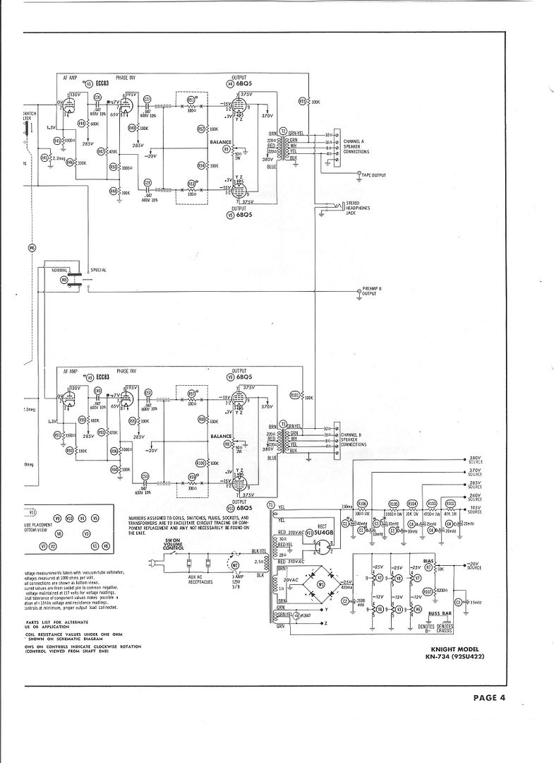
I've heard that schematics for old Knight amps can be tough to track down. I do not have one for the model you own. I do have half a schematic for a KN734, and a uselessly small photograph of the schematic for a KA55. Both of these amps are somewhat similar to the KN928 in that the use the same complement of output tubes (four 6BQ5). Perhaps there is enough similarity in the circuits for these to be of some use to you. Good luck.

Hi Kirk,
Since you've done the first obvious thing which is changing tubes, the next thing would be to open it up and check voltages around the power supply. You will need a voltmeter or multimeter of some kind. Begin by looking for dark or discolored resistors. Especially any that are connected to the filter capacitors or elsewere.
Voltages coming off the 6CA4 and the first filter cap should be over 300 volts, and progress slightly downward as you get farther away from there. If you find a serious voltage letdown somewhere, you will then need to determine why. Is it a bad resistor that has increased in value because of age, or because of something else like a leaky capacitor.
If you don't have a multimeter, you'll need to buy or borrow one. This is something you should have anyway at your disposal. So for now, voltage checks are the next logical step in trouble shooting. Since both channels are affected, the PS is the most likely place to start
Victor
Ty-
Thanks for the schematic. It does look similar to the KN928.
Victor-
I do have a Fluke DMM (without capacitance checker), a variac, and an old B&K single trace scope. Looking at buying a capacitor checker; is the one in a DMM good enough? Or for large filter caps used in old tube stuff do I need something else?
I will check the voltages (carefully)
Thanks
Kirk
You don't need a capacitor tester to trouble shoot this amp. Your scope will tell you if the filter capacitors are ok by looking at the ripple on the B+. Use a 10X probe with the scope input set to AC to keep the trace from shifting up off screen. If you connect a small test speaker to the amp, your ears will tell you much too. A small amount of ripple right out of the rectifier is normal and should smooth out to almost nothing at the next node.
Those small cheap capacitance meters are not very good for the most part because they only measure by the low voltage DC charging or time constant method. But they will tell you if a cap is probably ok or bad. They have no means of testing for leakage which requires higher voltage across the cap.
Victor
Korey-
I used the same 6CA4 in a Pilot 680 tuner and it worked fine
(good volume, etc) so I think it's OK.
Is that a sufficient test?
I tested the voltage coming off the secondary, and it's
544v, off the first filter cap it's 305, off the second 303v.
This is all new to me, but from what I've been reading for the 12AX7 and EL84, it looks like 250-300 volts is typical for the plate voltages but so far I haven't checked those, I assume that's the next thing to check? To be honest I'm a little spooked by the FAQs about guys getting fried working on these things, but I'm using one hand, clipping one lead, etc....I'm just going to have to get used to it.
I have the following tube gear
Pilot SA260 amp
Pilot SP210 Pre
Pilot SP216 Pre
Pilot 680 Tuner
Pilot FM200 Multiplexer
Knght KN928 intergrated
(2) Altec Lansing 1569a monoblocks
Altec Lansing 1566a mic amp
Dyanco PAS2
This was all given to me over the past 30 years as transistors replaced all the 'old junk' and I was the only one who was interested in taking it.
ALL of this stuff needs some kind of work, and I'd like to be able to do some of it myself. The Pilot amp is the only piece that has been recapped (not by me).
Thanks
Kirk
As Victor suggested I checked the voltages.
Here's what I got (correct me if I have the terminology wrong):
voltage coming off the secondary is 544v
Off the first filter cap it's 305
off the second filter cap 303v
On 1st preamp 12ax7 tube:
Pin1 (looks like plate from data sheet) 240v
Pin 6 (the other plate) 140
2nd 12ax7
Pin1 237v
Pin6 138
3rd 12ax7
Pin1 ~118 < ---these voltages jump around
Pin6 ~128 < ---these voltages jump around
4th 12ax7
Pin1 111 <----is this low for a 12ax7?
pin 6 102
On the 1st el34 :
pin 7 (looks like plate from the data sheet) 318 v
pin 9 (grid 2) 292v
2nd el34
pin 7 325v
pin 9 292v
3rd el34
pin 7 323
pin 9 299
4th el34
pin 7 318
pin 9 300
can we conclude anything from this? The voltages on the
third 12ax7 jump around, might this indicate a bad
element (resistor or capacitor?)
I suppose it would be easier to take it to the shop but it
looks like a simple enough unit that I (maybe) can fix with
some help from this forum. Also it's not worth a zillion dollars if I screw it up....
Again I don't have a schematic. I do have the one for the KN734
that Ty provided, but the resistance values for the KN734 are different than for the 928 that I have, and it uses a different rectifier tube.
Thanks for any advice you can offer.
Kirk
Wandering voltages might indicate you simply didn't get a good connection with your meter's probe. I wouldn't conclude anything at this point.
Your output tubes are EL84, not EL34.
It's OK to run 100 volts on the plate of a 12AX7.
Old resistors tend to drift upwards in value, especially the old carbon composition types. This can put an amp out of the "ideal" operating area, but usually isn't fatal. Some resistors can overheat, burn, or open completely. These should be easy to spot.
Old capacitors tend to "leak". A healthy capacitor shouldn't have less than (?) 100k ohms DC resistance across it. If the amplifier is powered off and the big caps in the power supply have been drained of any high voltage, you can stick an ohmmeter across the cap. Analog ohmmeters are easier to use here. The cap will initially show a low DC resistance, then it should quickly move towards a very high DC resistance as the cap charges up.
Leaking caps in the power supply cause humming. Leaking coupling caps (like C26, C27, and C28 in the KN734 schematic) allow DC from one stage to pass to the next. This can cause a tube to be driven into saturation.
You've checked the plate (anode) voltages on all the tubes, and the screen voltage on the EL84. Now it would be useful to check the grid and cathode voltages too. Cathode voltages must be much lower than anode voltages. Grid voltages must be lower than cathode voltages (sometimes even negative). If you have a leaking coupling cap (described above) you'll probably see a "bad" voltage on somebody's grid.
EL84
7 = anode (plate)
9 = screen
2 = grid
3 = cathode
12AX7
1 = 1st anode
2 = 1st grid
3 = 1st cathode
6 = 2nd anode
7 = 2nd grid
8 = 2nd cathode
Ty-
I am really grateful you've taken the time to look at this...
Yes of course, these are EL84 tubes in this amp (the Pilot has EL34s).
So I poked around and got the other readings:
12ax7 (1)
pin2 21v
pin3 60v
pin7 0 (makes some buzzing noise, not through the speakers,
when I take this reading...did I fry something?)
pin8 1 v
12ax7 (2)
pin2 19v
pin3 60v
pin7 .002v (same buzz as above)
pin8 1v
12ax7 (3)
pin1 0v
pin3 0.7v
pin7 -0.06v (no buzz)
pin8 0.58v
12ax7 (4)
pin2 0.001v
pin2 0.7 v
pin7 -0.02v (no buzz)
pin8 0.63v
EL84 (1)
pin 2 .065v
(BTW this pin is not connected to anything on this one tube, but it is on the other three EL84)
pin 3 10.4 v
EL84 (2)
pin2 .007v
pin3 9.42 v
EL84 (3)
pin2 varies between -.001 and +.002v
pin3 9.54 v
EL84 (4)
pin2 .022v
pin3 9.53v
I made up a discharger resistor (these filter caps hold >20v
for several hours) and drained the caps.
the first filter cap has three 20uf elements and one 10 uf.
The three 20uf caps measure >13M ohms.
The 10uf (which is connected to ground via a 100 ohm resistor)
has DC resistance of ...100 ohms. according to the can the 10uf
cap is only rated for 50v, the others rated to 350v.
The second filter cap has 2 10uf elements and they
show DC resistance of over 13Mohms. I do not hear any hum when using the amp.
Do these reading sound right?
On a whim I checked the volume control, and it looks OK....
Thanks again
Kirk
None of the voltages you measured look out of place to me. Maybe one of our cleverer readers can spot something.
Your EL84 output tubes are biased differently from the schematic shown for the KN734. While the KN734 is predominately "fixed bias", yours is purely cathode biased (also known as self bias, or auto bias). See the "-20V SOURCE" on the lower right corner of the KN734 schematic? This negative supply is fed onto the grids of the output tubes. This keeps them lower than the cathodes and biases the tubes.
Your amp apparently does not have such a fixed bias supply. Instead, the cathodes are kept at a positive voltage (above the grids) by means of a resistor between cathode and ground. It is almost certainly the 100 ohm resistor you spotted attached to one of the caps. Most likely, that 100 ohm resistor is connected to all four EL84 cathodes. It is common practice to "bypass" such a cathode resistor with a capacitor. The bypass capacitor allows AC signals through the tube to be shorted to ground. The gain of the tube will be lower without the bypass cap. It may also affect frequency response of the circuit (can't remember). Look here for an example of four EL84 output tubes sharing a common cathode resistor (R13) which is bypassed with a cap (C80):
http://www.geocities.com/vintageaudio/st35a.jpg
I'm concerned that you say the grid (pin 2) of one of the EL84 isn't connected to anything. I'm thinking pins 1 and 2 are internally connected on the tube. Perhaps pin 1 is wired up in a manner similar to pin 2 on the other three tubes?
Now I really wish I had a schematic for your exact model of amp. I'm trying to guess how it's wired up based on the voltages you are seeing. Out of the four 12AX7 tubes you've got, I'm guessing that one half of one tube is being used as an audio frequency amplifier (call it an AF amp, gain stage, or preamp) and the other half of the same tube is getting used as a cathodyne phase splitter... or is it a paraphase splitter? You'll need this arrangement for each side (left and right), so that takes care of two of the tubes. If they did it this way on your amp, it would be something similar to what you see on V3 and V8 of the KN734.
The other two 12AX7 are probably used for the phono preamp or for providing additional gain needed to overcome insertion losses from the bass and treble controls.
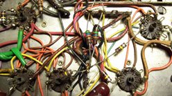
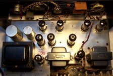
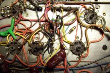
I'll keep thinking on this one. Don't give up hope yet. I'm sure the solution will be fairly simple, once it is found. Do you have access to a digital camera? A couple of closeup photos of the wiring underneath the chassis, as well as a photo of the layout from the top might be helpful.
Your EL84 output tubes are biased differently from the schematic shown for the KN734. While the KN734 is predominately "fixed bias", yours is purely cathode biased (also known as self bias, or auto bias). See the "-20V SOURCE" on the lower right corner of the KN734 schematic? This negative supply is fed onto the grids of the output tubes. This keeps them lower than the cathodes and biases the tubes.
Your amp apparently does not have such a fixed bias supply. Instead, the cathodes are kept at a positive voltage (above the grids) by means of a resistor between cathode and ground. It is almost certainly the 100 ohm resistor you spotted attached to one of the caps. Most likely, that 100 ohm resistor is connected to all four EL84 cathodes. It is common practice to "bypass" such a cathode resistor with a capacitor. The bypass capacitor allows AC signals through the tube to be shorted to ground. The gain of the tube will be lower without the bypass cap. It may also affect frequency response of the circuit (can't remember). Look here for an example of four EL84 output tubes sharing a common cathode resistor (R13) which is bypassed with a cap (C80):
http://www.geocities.com/vintageaudio/st35a.jpg
I'm concerned that you say the grid (pin 2) of one of the EL84 isn't connected to anything. I'm thinking pins 1 and 2 are internally connected on the tube. Perhaps pin 1 is wired up in a manner similar to pin 2 on the other three tubes?
Now I really wish I had a schematic for your exact model of amp. I'm trying to guess how it's wired up based on the voltages you are seeing. Out of the four 12AX7 tubes you've got, I'm guessing that one half of one tube is being used as an audio frequency amplifier (call it an AF amp, gain stage, or preamp) and the other half of the same tube is getting used as a cathodyne phase splitter... or is it a paraphase splitter? You'll need this arrangement for each side (left and right), so that takes care of two of the tubes. If they did it this way on your amp, it would be something similar to what you see on V3 and V8 of the KN734.
The other two 12AX7 are probably used for the phono preamp or for providing additional gain needed to overcome insertion losses from the bass and treble controls.
I'll keep thinking on this one. Don't give up hope yet. I'm sure the solution will be fairly simple, once it is found. Do you have access to a digital camera? A couple of closeup photos of the wiring underneath the chassis, as well as a photo of the layout from the top might be helpful.
I'm not sure if this helps, or just further confuses the issue. Regardless, here's another schematic for you to stare at and think about. It's another push/pull EL84 design. An ECC83 tube is the same as a 12AX7.
http://www.schematics.ca/modules/PDdownloads/singlefile.php?cid=68&lid=487
http://www.schematics.ca/modules/PDdownloads/singlefile.php?cid=68&lid=487
I'm staring at your voltages, and assuming the 12AX7 you've numbered #1 and #2 must be the AF amp and phase splitter. I say this because they're the ones with the high(er) voltages on them.
Can you check if pins 1 and 3 (plate and cathode) of these 12AX7 are connected to the EL84 output tubes? There will almost certainly be a capacitor in series between them.
If so, I'm trying to figure out why you are reading 20 volts on the grid of these tubes. If the circuit is anything like V3/V8 in the KN734, or V4/V7 in the A230, I'd think that grid should be a lot closer to zero volts (or slightly negative).
I need to learn to read the schematics a little more carefully, or at least not look at them too late at night. The PI (phase inverter) shown in both the KN734 schematic and the A230 schematic is a cathodyne. The little square block next to the indicated voltage on the grid refers to a note which (unfortunately) you can't see on the KN734 drawing. Basically, it says the -0.7 volts is measured with respect to the cathode, not ground.
I'm reasonably sure you've got tube #1 for one channel (left or right) and tube #2 for the other. The first triode in that tube (pins 1, 2, 3) is the cathodyne PI. The second triode (pins 6, 7, 8) are the AF amp. The question now is why is the grid (pin 2) 40 volts lower than the cathode (pin 3)? It should be less than one volt lower, not 40.
See if you can use the KN734 schematic as a template, and try to sketch out the wiring around tube #1 on your amp. If you can make out the color codes, read the resistor values of your amp and mark up the schematic. Hopefully, there should be some similarity between your tube #1 and V3 on the KN734.
Ty-
Once again I thank you for spending time helping me with this!
I will take your points in order:
>Most likely, that 100 ohm resistor is connected to all four EL84 cathodes
yes, it looks like that goes to pin 3(cathode) on all of the EL84.
Those are the yellow wires in the pics. Is it possible the bypass capacitor is the 50uf 50v cap that's in the can with the three larger ones?
> I'm concerned that you say the grid (pin 2) of one of the EL84 >isn't connected to anything. I'm thinking pins 1 and 2 are >internally connected on the tube. Perhaps pin 1 is wired up in a > manner similar to pin 2 on the other three tubes?
Yes, that looks to be the case. Hopefully you can confirm from the pics. You must have a lot of experience with these circuits
(or a REALLY good guesser!)
Thanks for the HK230 schematic. Is this one closer to the KN928?
> Can you check if pins 1 and 3 (plate and cathode) of these >12AX7 are connected to the EL84 output tubes? There will >almost certainly be a capacitor in series between them.
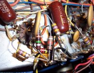
Yes they are connected to the grid of the EL84 (pin2 on three of them, pin 1 on the other one) via a .047 ufd 600w caps (the large brown ones in the pics)
One thing I did find was there is a 47K resistor connected to
the 16ohm speaker tap that is broken. I have never used the 16 ohm tap so I don't know if this matters, still should be replaced.
BTW what power rating would these resistors be?
I have a lot of 1/4 watt resistors but those would be too small I'd think....
I hope the jpg is OK, file size is a constraint.
Kirk
Once again I thank you for spending time helping me with this!
I will take your points in order:
>Most likely, that 100 ohm resistor is connected to all four EL84 cathodes
yes, it looks like that goes to pin 3(cathode) on all of the EL84.
Those are the yellow wires in the pics. Is it possible the bypass capacitor is the 50uf 50v cap that's in the can with the three larger ones?
> I'm concerned that you say the grid (pin 2) of one of the EL84 >isn't connected to anything. I'm thinking pins 1 and 2 are >internally connected on the tube. Perhaps pin 1 is wired up in a > manner similar to pin 2 on the other three tubes?
Yes, that looks to be the case. Hopefully you can confirm from the pics. You must have a lot of experience with these circuits
(or a REALLY good guesser!)
Thanks for the HK230 schematic. Is this one closer to the KN928?
> Can you check if pins 1 and 3 (plate and cathode) of these >12AX7 are connected to the EL84 output tubes? There will >almost certainly be a capacitor in series between them.
Yes they are connected to the grid of the EL84 (pin2 on three of them, pin 1 on the other one) via a .047 ufd 600w caps (the large brown ones in the pics)
One thing I did find was there is a 47K resistor connected to
the 16ohm speaker tap that is broken. I have never used the 16 ohm tap so I don't know if this matters, still should be replaced.
BTW what power rating would these resistors be?
I have a lot of 1/4 watt resistors but those would be too small I'd think....
I hope the jpg is OK, file size is a constraint.
Kirk
Attachments
>See if you can use the KN734 schematic as a template, and try >to sketch out the wiring around tube #1 on your amp. If you can >make out the color codes, read the resistor values of your amp >and mark up the schematic. Hopefully, there should be some >similarity between your tube #1 and V3 on the KN734.
OK I'll give this a shot. Here is a pic of that tube.
OK I'll give this a shot. Here is a pic of that tube.
Attachments
> Once again I thank you for spending time helping me with this!
No problem. I've had a peculiar fascination with EL84, so I've collected a bunch of information on them.
>yes, it looks like that goes to pin 3(cathode) on all of the EL84.
>Those are the yellow wires in the pics. Is it possible the bypass
>capacitor is the 50uf 50v cap that's in the can with the three larger
>ones?
The 50 volt cap is definitely the cathode bypass. I thought last time you said it was 10uF, which sounded too small. 50uF is a reasonable size. This cap shouldn't ever see more than about 10~15 volts, so the 50v rating is just fine. Just watch out that this cap doesn't ever go leaking too much. If it shorts to ground, the output tubes won't have enough bias on them and they'll conduct too much. You might see the plates on the EL84 start to glow cherry red if this happens.
>Yes, that looks to be the case. Hopefully you can confirm from the
>pics. You must have a lot of experience with these circuits
>(or a REALLY good guesser!)
Mostly a good guesser. I wish I had more experience with these designs, but I was born after the golden age of tubes. It's that perverse fascination I mentioned above that drives me to learn about them. You can figure out an awful lot of stuff with the help of guys from the forums and Google. It doesn't hurt that a lot of these amps seem to share a very similar design.
> Thanks for the HK230 schematic. Is this one closer to the KN928?
It's hard to say. I still don't know exactly how the KN928 is wired. I know the output stage is cathode biased (like the A230) and not fixed biased (like the KN734). I expect all three of these amps have similar AF/PI designs, utilizing a single 12AX7. I know the A230 uses 12AU7 tubes in the phono and tone control sections, while your amp has no 12AU7. So, no, it still isn't an exact match for yours.
>One thing I did find was there is a 47K resistor connected to
>the 16ohm speaker tap that is broken. I have never used the 16
>ohm tap so I don't know if this matters, still should be replaced.
>BTW what power rating would these resistors be?
>I have a lot of 1/4 watt resistors but those would be too small I'd
>think....
Could a big problem there. I'm thinking the 47K resistor you are looking at is connected more or less like R55 on the KN734 circuit. You'll also find it in the A230 design at R22. That's a negative feedback (NFB) loop. It takes a sample of the signal from the output of the amp, and feeds it back into the input out of phase. It reduces distortion, lowers the overall gain of the amp, and dramatically improves the output impedance (and damping factor) of the amp. Triode designs can get away with little or no NFB, but in pentode amps it is almost a necessity.
Worst case would be if that resistor is a dead short, but I'd expect the amp would become an oscillator, howling and squealing horribly. If it went open circuit, you should have a lot more gain (louder) but lousy bass response.
>I hope the jpg is OK, file size is a constraint.
It's tough to make anything out from the tiny picture. Try hosting the original photo at a site like Photobucket.com. Make an account, click on the links to upload your pictures, check the box under your uploaded photo, then press the button at the bottom labelled "Generate HTML and IMG code". Then copy the link in the box titled "IMG clickable thumbnails for message boards - recommended" and paste it into your reply.
Ty-
OK I've uploaded the pics to Photobucket:
A couple of things: I was right the first time, the bypass cap is 10uf 50v, not 50uf.
If I replace the 47k resistor, what power rating should I get?
Is quality an issue here? (i.e. metal film vs carbon vs unobtainium
$50 resistors from the back of the Absolute Sound?)
Looking at the KN-734, I see what looks like 2 12ax7s, but that's actually one isn't it? The diagram shows each one as a triode,
but this tube is a dual triode as I understand. Am I reading this right?
I'm gonna owe you a case of beer (assuming you like beer that is)
Thanks
Kirk
OK I've uploaded the pics to Photobucket:
An externally hosted image should be here but it was not working when we last tested it.
An externally hosted image should be here but it was not working when we last tested it.
An externally hosted image should be here but it was not working when we last tested it.
An externally hosted image should be here but it was not working when we last tested it.
An externally hosted image should be here but it was not working when we last tested it.
A couple of things: I was right the first time, the bypass cap is 10uf 50v, not 50uf.
If I replace the 47k resistor, what power rating should I get?
Is quality an issue here? (i.e. metal film vs carbon vs unobtainium
$50 resistors from the back of the Absolute Sound?)
Looking at the KN-734, I see what looks like 2 12ax7s, but that's actually one isn't it? The diagram shows each one as a triode,
but this tube is a dual triode as I understand. Am I reading this right?
I'm gonna owe you a case of beer (assuming you like beer that is)
Thanks
Kirk
- Status
- This old topic is closed. If you want to reopen this topic, contact a moderator using the "Report Post" button.
- Home
- Amplifiers
- Tubes / Valves
- Very low output from Knight KN928 amp